Table of Contents
Advertisement
CAUTION: Failure to read and follow all installation and operating instructions could lead to personal injury and/
or damage to property.
CAUTION: All electrical installations must comply with local building and safety codes and must be performed by
qualified personnel only.
System Overview
• This control system is intended to be used with an evaporative cooler with a 2-speed blower and a water pump. It will also operate a
water purge pump or valve, if equipped.
• The control is designed for fan motors up to 1HP (120V) or 2HP (240V), with water pump and purge pump up to 2A (120V) or 1A
(240V)
• The fan motor may be 120V or 240V rated.
• The water pump and purge pump motors/valves share the same electrical supply, rated for 120V or 240V.
Included in Kit
• Wall Control Thermostat
• 2-Speed Evaporative Cooler Control
• Wire Nut for common Earth connection.
• Spare 3.15 Amp fuse for control.
• Jumper wire for Link to N-Link (To be used only when both Fan and Pump voltages are the same).
Additional Requirements
Depending on application and installation, the following additional items may be required:
• Screws or bolts for mounting the Appliance Control Box and Wall Control
• Wiring for connection between power supply and Appliance Control Box; Wall Control and Appliance Control Box; and between
Appliance Control Box and the cooler connection box.
• Conduit and watertight connectors to protect all wiring.
Installation of the Appliance Control Box
CAUTION: To prevent electrical shock and/or damage to the equipment, disconnect electrical power to the system at
the main fuse or circuit breaker before starting the installation, and leave disconnected until the installation is complete.
1) After determining a suitable place to install the Appliance Control Box, mark the location of the three mounting points (with the
'TOP' indication uppermost) and drill pilot holes for the mounting screws.
2) Determine which knockout locations will be used for the system wiring.
3) Using a suitable tool, cut out the required knockouts. Make sure you cut out the
correct size hole for your fitting.
4) Mount the box using suitable screws.
5) Install conduit and connections, ensuring a watertight seal, especially around the
locations where the knockouts were removed.
6) Run wiring, in accordance with local and national electrical codes, to suit the
installation.
7) Connect the wires in accordance with the wiring diagram on next page (wiring
diagram also located on the inside lid of Appliance Control box).
WARNING: Use the jumper wire between Link and NLink only
when fan and pump voltages are the same.
Wall Control Thermostat and 2-Speed Evaporative Cooler
Control System • Model 110423-2
Installation Instructions
Advertisement
Table of Contents

Subscribe to Our Youtube Channel
Summary of Contents for MasterStat 110423-2
-
Page 1: Installation Instructions
Wall Control Thermostat and 2-Speed Evaporative Cooler Control System • Model 110423-2 Installation Instructions CAUTION: Failure to read and follow all installation and operating instructions could lead to personal injury and/ or damage to property. CAUTION: All electrical installations must comply with local building and safety codes and must be performed by qualified personnel only. -
Page 2: Installation Of Wall Control
Wiring Connections in Appliance Control Box Wiring Connections - Use Copper Conductors Fan/Pump 120V Fan/Pump 240V Fan 240V Pump 120V Fan 120V Pump 240V Power Supply Pump Purge *Note: Use the provided wire nut to connect all ground connections for power supply, fan, pump, purge pump and cooler cabinet. -
Page 3: Operating Instructions
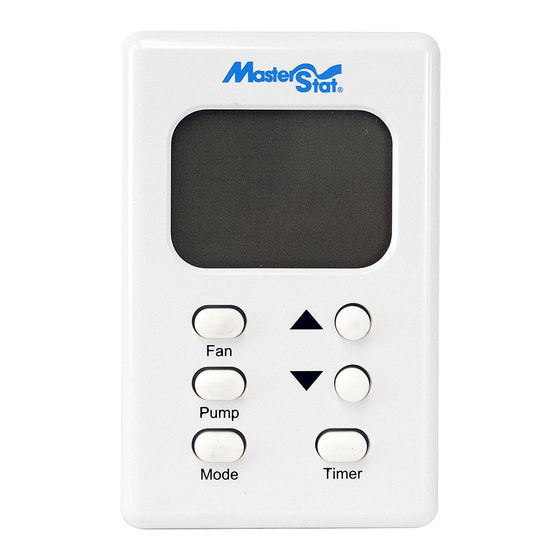
Operating Instructions Automatic Operation The fan and water pump are controlled automatically to achieve the desired comfort level. Automatic operation is activated by pressing the ‘Mode’ button until ‘Auto’ is displayed on the LCD. The ‘Mode’ button changes the control between Off, Auto and Manual. The Set temperature (the target temperature for the control) may be altered by repeatedly pressing or holding the ‘Up’ and ‘Down’ but- tons. The LCD will display ‘Set’ rather then ‘Room’ temperature for a short time after pressing the ‘Up’ or ‘Down’ button. On starting, if the pads in the cooler are too dry, the fan may be delayed from starting until the pads have absorbed some water. This is called Pre-Wet and lasts for 2 minutes, indicated by ‘Pre-Wet” flashing on the LCD. The Pre-Wet can be bypassed by entering manual mode by either pressing the ‘Fan’, ‘Pump’ or ‘Mode’ button and then pressing the ‘Mode’ button until ‘Auto’ is displayed. During automatic operation, the control performs a water purge cycle every 8 or 12 hours of pump operation. This interval can be toggled between 8 or 12 hours by simultaneously holding the ‘Pump’ and ‘Fan’ buttons for 5 seconds. The selected interval is displayed for a short time. Press the Up or Down arrow buttons to change between 8 or 12 hours. This action also starts a manual purge cycle. A purge pump or purge valve, which is not supplied with the thermostat control or evaporative cooler, is required for this operation. Manual Operation The fan speed and pump are set by the user. To activate the manual mode from the ‘Off’ state, press the ‘Mode’ button until ‘Manual is displayed. If the control is in the ‘Auto’... -
Page 4: Trouble Shooting Guide
Trouble Shooting Guide The guide below is intended to aid an Installer or Service Technician in resolving simple problems. CAUTION: To prevent electrical shock and/or damage to the equipment, disconnect electrical power to the system at the main fuse or circuit breaker before opening the appliance control box, and leave disconnected until after the lid has been shut and secured. CAUTION: Any testing performed on live conductors must be carried out by qualified personnel only.
Need help?
Do you have a question about the 110423-2 and is the answer not in the manual?
Questions and answers