Table of Contents
Advertisement
ATTENTION: INSTALLING THE CONTROLLER WITH THE
!
DEFAULT SETTINGS IS NOT RECOMMENDED. IN
ORDER TO PREVENT OVERHEATING OF THE SYSTEM
HEAT EXCHANGER FLUID OR DOMESTIC HOT WATER
THE SETTINGS "OCC" AND "OSTC" SHOULD BE SET
TO "ON" AND THE SETTING "EM" SHOULD BE RAISED
TO 290 °F.
OPERATION AND INSTALLATION
SOLAR CONTROLLER
» SOM 7 PLUS
Advertisement
Chapters
Table of Contents

Summary of Contents for STIEBEL ELTRON SOM 7 PLUS
- Page 1 ORDER TO PREVENT OVERHEATING OF THE SYSTEM HEAT EXCHANGER FLUID OR DOMESTIC HOT WATER THE SETTINGS “OCC” AND “OSTC” SHOULD BE SET TO “ON” AND THE SETTING “EM” SHOULD BE RAISED TO 290 °F. OPERATION AND INSTALLATION SOLAR CONTROLLER » SOM 7 PLUS...
-
Page 2: Table Of Contents
Contents General ................2 System layout 8 ............24 Overview ................3 System-specific functions .......... 26 1. Installation ..............4 System layout 9 ............28 1.1 Mounting ..............4 System layout 10 ............30 1.2 Electrical connection ............ 4 2. Operation and function ..........32 1.3 Data communication/ Bus .......... -
Page 3: Overview
• Housing with outstanding design • Extra-low power consumption 2.6" Included with the SOM 7 plus: 66 mm 1 × SOM 7 plus 1 × accessory bag 1 × spare fuse T4A 2 × screws and wall plugs 4 ×... -
Page 4: Installation
1. Installation WARNING! Electric shock! 1.1 Mounting Opening the housing will expose live display parts! Î Switch off power supply and disconnect the device from power supply before opening the housing! The unit must only be installed push button • in a dry interior location cover •... -
Page 5: Data Communication/ Bus
Connecting the device to the power supply must always be the last step of the installation! The power supply to the controller must be carried out via an external power switch (last step!). The supply voltage must be 100 ... 240 V~ (50 ... 60 Hz). Flexible cables must be attached to the housing with the enclosed strain relief and the corresponding screws. -
Page 6: Terminal Allocation In The Different System Layouts
1.4 Terminal allocation in the different system layouts System layout 1 Sensors S3 and S4 can optionally be connected for The controller calculates the temperature difference between measurement purposes. collector sensor S1 and tank sensor S2. If the difference is larger than or identical to the adjusted switch-on temperature If energy metering (OHQM) is activated, sensor S4 has to be connected as return sensor. - Page 7 Adjustment Channels Channel Description Factory setting Page System DT O Switch-on temperature difference 12.0 °Ra [6.0 K] DT F Switch-off temperature difference 8.0 °Ra [4.0 K] DT S Nominal temperature difference 20.0 °Ra [10.0 K] Rise control R1 4 °Ra [2 K] Minimum pump speed 30 % S MX...
-
Page 8: System Layout 2
System layout 2 Heat exchange from tank 1 to tank 2 will be operated by relay The controller calculates the temperature difference between 2, if the temperature difference between sensors S3 and S4 is collector sensor S1 and tank sensor S2. If the difference is larger than or identical to the adjusted switch-on temperature larger than or identical to the adjusted switch-on temperature difference (DT O), the solar pump will be operated by relay 1,... - Page 9 Adjustment Channels Channel Description Factory setting Page System DT O Switch-on temperature difference 12.0 °Ra [6.0 K] DT F Switch-off temperature difference 8.0 °Ra [4.0 K] DT S Nominal temperature difference 20.0 °Ra [10.0 K] Rise control R1 4 °Ra [2 K] n1MN Minimum pump speed R1 30 %...
-
Page 10: System-Specific Functions
System-specific functions The following adjustments are used for the specific function in system layout 2. ∆T control for the heat exchange between 2 tanks Reference sensors for this function are S3 and S4. DT3O: Switch-on temperature diff. In system layout 2 the controller is equipped with an ad- Adjustment range: 2.0 ... - Page 11 Maximum temperature limitation Minimum and maximum temperature limits can be set for the heat exchange function. The maximum temperature limitation uses sensor 4 as MX3O / MX3F: reference sensor. Maximum temperature limitation Adjustment range: The maximum temperature limitation function provides a 30.0 ...
-
Page 12: System Layout 3
System layout 3 The controller calculates the temperature difference between relay 2 for backup heating or heat dump purposes, when collector sensor S1 and tank sensor S2. If the difference is the adjusted thermostat switch-on temperature (AH O) is larger than or identical to the adjusted switch-on temperature reached. - Page 13 Adjustment Channels Channel Description Factory setting Page System DT O Switch-on temperature difference 12.0 °Ra [6.0 K] DT F Switch-off temperature difference 8.0 °Ra [4.0 K] DT S Nominal temperature difference 20.0 °Ra [10.0 K] Rise control R1 4 °Ra [2 K] n1MN Minimum pump speed R1 30 %...
-
Page 14: System-Specific Functions
The following functions are exclusively available in system System-specific functions layout 3. The corresponding channels will not be available in any other system layout. Thermostat function The thermostat function works independently from the solar Backup heating operation and can be used for using surplus energy or for backup heating. - Page 15 Option: Thermal disinfection of the upper DHW zone (OTD) OTD: This function is used for protecting the upper tank zone against Thermal disinfection function Legionella by activating the backup heating. Adjustment range: ON / OFF Reference sensor for the thermal disinfection is S3! Factory setting: OFF Î...
-
Page 16: System Layout 4
System layout 4 The controller calculates the temperature differences between reached. The priority logic causes priority loading of the upper collector sensor S1 and tank sensors S2 and S3. If the zone of the tank, if possible. The 3-way-valve will be operated differences are larger than or identical to the adjusted switch- by relay 2 then. - Page 17 Adjustment Channels Channel Description Factory setting Page System Minimum pump speed 30 % DT1O Switch-on temperature difference 1 12.0 °Ra [6.0 K] DT1F Switch-off temperature difference 1 8.0 °Ra [4.0 K] DT1S Nominal temperature difference 1 20.0 °Ra [10.0 K] RIS1 Rise control R1 4 °Ra [2 K]...
-
Page 18: System Layout 5
System layout 5 The controller calculates the temperature differences between The priority logic causes priority loading of tank 1, if possible. collector sensor S1 and tank sensors S2 and S3. If the For loading tank 2 the 3-way-valve will be operated by relay 2. differences are larger than or identical to the adjusted switch- Sensor S4 can optionally be connected for measurement on temperature differences (DT1O / DT2O), the solar pump will... - Page 19 Adjustment Channels Channel Description Factory setting Page System Minimum pump speed 30 % DT1O Switch-on temperature difference 1 12.0 °Ra [6.0 K] DT1F Switch-off temperature difference 1 8.0 °Ra [4.0 K] DT1S Nominal temperature difference 1 20.0 °Ra [10.0 K] RIS1 Rise control R1 4 °Ra [2 K]...
-
Page 20: System Layout 6
System layout 6 The controller calculates the temperature differences (S1MX / S2MX) are reached. The priority logic causes priority between collector sensor S1 and tank sensors S2 and S3. If loading of the selected tank (PRIO), if possible. Loading both the differences are larger than or identical to the adjusted tanks simultaneously is possible as well (PRIO = 0). - Page 21 Adjustment Channels Channel Description Factory setting Page System DT1O Switch-on temperature difference 1 12.0 °Ra [6.0 K] DT1F Switch-off temperature difference 1 8.0 °Ra [4.0 K] DT1S Nominal temperature difference 1 20.0 °Ra [10.0 K] RIS1 Rise control R1 4 °Ra [2 K] n1MN Minimum pump speed R1 30 %...
-
Page 22: System Layout 7
System layout 7 be loaded until the switch-off temperature difference (DT F) or The controller calculates the temperature differences between the maximum tank temperature (S MX) is reached. the collector sensors S1 and S3 and the tank sensor S2. If the differences are larger than or identical to the adjusted switch- Sensor S4 can optionally be connected for measurement on temperature difference (DT O), the respective solar pump... -
Page 23: Symbol
Adjustment Channels Channel Description Factory setting Page System DT O Switch-on temperature difference 12.0 °Ra [6.0 K] DT F Switch-off temperature difference 8.0 °Ra [4.0 K] DT S Nominal temperature difference 20.0 °Ra [10.0 K] Rise control R1 / R2 4 °Ra [2 K] n1MN Minimum pump speed R1... -
Page 24: System Layout 8
System layout 8 The controller calculates the temperature difference between A solid fuel boiler will be operated by relay 2, if the collector sensor S1 and tank sensor S2. If the difference is temperature difference between sensors S4 and S3 is larger larger than or identical to the adjusted switch-on temperature than or identical to the adjusted switch-on temperature difference (DT O), the solar pump will be operated by relay 1,... - Page 25 Adjustment Channels Channel Description Factory setting Page System DT O Switch-on temperature difference 12.0 °Ra [6.0 K] DT F Switch-off temperature difference 8.0 °Ra [4.0 K] DT S Nominal temperature difference 20.0 °Ra [10.0 K] Rise control R1 4 °Ra [2 K] n1MN Minimum pump speed R1 30 %...
-
Page 26: System-Specific Functions
System-specific functions The following adjustments are used for the specific functions in system layout 8. ∆T control for backup heating by solid fuel boiler Reference sensors for this function are S4 and S3. In system layout 8, the controller is equipped with an ad- DT3O: ditional differential control for heat exchange from a solid Switch-on temperature diff. - Page 27 Maximum temperature limitation Minimum and maximum temperature limits can be set for the solid fuel boiler. MX3O / MX3F: The maximum temperature limitation function provides a Maximum temperature limitation maximum tem perature setting, usually to reduce scald risk Adjustment range: in a storage tank.
-
Page 28: System Layout 9
System layout 9 A heating circuit return preheating will be operated by relay The controller calculates the temperature difference between collector sensor S1 and tank sensor S2. If the difference is 2, if the temperature difference between sensors S3 and S4 is larger than or identical to the adjusted switch-on temperature larger than or identical to the adjusted switch-on temperature difference (DT O), the solar pump will be operated by relay 1,... - Page 29 Adjustment Channels Channel Description Factory setting Page System DT O Switch-on temperature difference 12.0 °Ra [6.0 K] DT F Switch-off temperature difference 8.0 °Ra [4.0 K] DT S Nominal temperature difference 20.0 °Ra [10.0 K] Rise control R1 4 °Ra [2 K] Minimum pump speed 30 % S MX...
-
Page 30: System Layout 10
System layout 10 The controller calculates the temperature difference between be operated by relay 2 in order to direct the surplus energy to a heat dump. For security purpose this will be carried out only if collector sensor S1 and tank sensor S2. If the difference is larger than or identical to the adjusted switch-on temperature the tank temperature is below the non-adjustable emergency difference (DT O), the solar pump will be operated by relay 1,... - Page 31 Adjustment Channels Channel Description Factory setting Page System DT O Switch-on temperature difference 12.0 °Ra [6.0 K] DT F Switch-off temperature difference 8.0 °Ra [4.0 K] DT S Nominal temperature difference 20.0 °Ra [10.0 K] Rise control R1 4 °Ra [2 K] Minimum pump speed 30 % S MX...
-
Page 32: Operation And Function
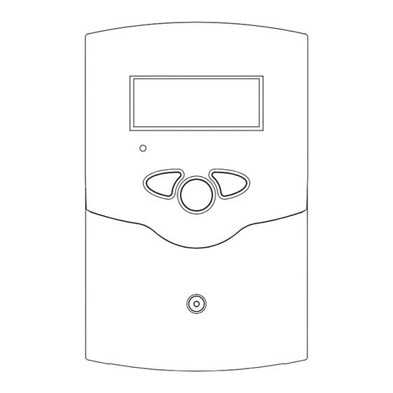
2. Operation and function The controller is operated via three push buttons below the display. Button 1 is used for scrolling forward through the 2.1 Push buttons indication menu or to increase the adjustment values. Button 2 is used for scrolling backward and reducing values. During normal operation, only the display channels are shown. -
Page 33: Flashing Codes
System screen The system screen (active system layout) shows the system selected on the controller. It consists of several system component symbols, which are – depending on the current status of the system – either flashing, permanently shown or hidden. system screen tank sensor sensors... -
Page 34: Commissioning
Operating the commissioning menu: Î Enter the channel by pressing button 3 symbol flashes. The three pushbuttons of the SOM 7 plus controller Î Adjust the value by pressing buttons 1 and 2 Î Save the adjustment by pressing button 3 again symbol stops flashing. - Page 35 Arr: 4. System layout System layout selection Î Adjust the desired system layout of your solar thermal Adjustment range: 1 ... 10 system Factory setting: For a detailed description of the different system layouts selectable, see chapter 1.4. Overview of system layouts: Arr 1 Arr 2 Arr 1 :...
- Page 36 S MX / S1MX / S2MX: 5. Maximum tank temperature Maximum tank temp. Î Adjust the desired maximum tank temperature Adjustment range: 40 ... 200 °F [4 ... 95 °C] Note: Arr 10: The controller is also equipped with a non- 40 ...
-
Page 37: Channel Overview
4. Channel overview 4.1 Display channels Note: The displayed values and adjustment channels depend on which system layout, which options and functions have been selected. Only values and adjustment channels available for the individual Indication of drainback time periods settings selected will appear in the menu. Initialization Indicates the time adjusted in tDTO, running backwards. - Page 38 Indication of current pump speed Indicates the current pump speed of the corresponding pump. • n % : current pump speed (1-pump system) n %, n1 %, n2 %: • n1 % : current pump speed pump 1 Current pump speed •...
-
Page 39: Adjustment Channels
4.2 Adjustment channels In this channel, a pre-defined system layout can be selected. System layout selection Each system layout has a set of pre-programmed settings that Arr: can be individually changed. System layout selection. If the system layout selection is changed later on, all Adjustment range: 1 ... - Page 40 Maximum tank temperature Once the adjusted maximum temperature is exceeded, S MX / S1MX / S2MX: the solar pump is switched off and further loading of the Maximum tank temp. tank is prevented to reduce scald risk or system damage. A Adjustment range: fixed hysteresis of 4 °Ra [2 K] is set for the maximum tank 40 ...
- Page 41 Cooling functions In the following the three cooling functions – collector cooling, system cooling and tank cooling – are described in detail. The following notes are valid for all three cooling functions: Note: The cooling functions will not become active as long as solar loading is possible.
- Page 42 Tank cooling function When the tank cooling function is activated, the controller aims to cool down the tank during the night in order to prepare it for OSTC: solar loading on the following day. Tank cooling option If the adjusted maximum tank temperature (S MX / S1MX) is Adjustment range: OFF / ON exceeded and the collector temperature falls below the tank Factory setting: OFF...
- Page 43 If a multi-tank system layout has been chosen, the priority The SOM 7 plus priority logic logic determines how the heat is divided between the tanks. Note: Different types of priority logic are adjustable: Priority logic can be used in multi-tank system •...
- Page 44 Evacuated tube collector function O TC: This function helps overcome the disadvantages caused by the Evacuated tube collector non-ideal sensor position with some tube collectors. function This function operates within an adjusted time frame Adjustment range: OFF / ON (beginning at TCST and ending at TCEN). It activates the Factory setting: OFF collector circuit pump for an adjustable runtime (TCRU) between adjustable standstill intervals (TCIN) in order to...
- Page 45 Drainback option Note: A drainback system permits the heat transfer fluid to drain A drainback system layout requires additional back into the holding tank when solar energy is not collected. components such as a holding tank. The drainback The drainback option will initiate the filling of the system option should only be activated if all components when solar loading begins.
- Page 46 Operating mode For control and service work, the operating mode of the controller can be manually adjusted. For this purpose, select MAN1 / MAN2: the adjustment value MAN1, MAN2 in which the following Operating mode Adjustment adjustments can be made: range: OFF, Auto, ON Factory setting: Auto •...
-
Page 47: Troubleshooting
5. Troubleshooting fuse In the case of an error, a message is shown on the display of the controller: Warning symbols Operating control lamp VBus ® terminals sensor terminals load terminals ground terminals power supply terminals Operating control lamp off. Operating control lamp flashes red. -
Page 48: Various
5.1 Various: Pump is overheated, but no heat transfer from the collector Pump starts for a short moment, switches off, switches on to the tank, flow and return have the same temperature; again, etc. perhaps also air / gas bubbles in the lines. Air in the system? Temperature difference at Air in the system;... - Page 49 Tanks cool down at night Control the non-return Further pumps which are v a l v e i n w a rm w a t e r connected to the solar tank circulation - o.k. must also be checked. Collector circuit pump runs during the night? Check controller: Manual operation active?
- Page 50 Warranty Make any warranty claim in the country where you purchased the appliance. In such cases, please contact our representation or the importer. Our warranty applies only if: — These installation instructions have been observed — Exclusively accessories designated for this appliance have been used —...
- Page 52 Verkauf Tel. 0180 3 700705 | Fax 0180 3 702015 | info-center@stiebel-eltron.de 17 West Street | West Hatfield MA 01088 STIEBEL ELTRON GmbH & Co. KG Kundendienst Tel. 0180 3 702020 | Fax 0180 3 702025 | kundendienst@stiebel-eltron.de Tel. 4 13-247-3380 | Fax 413-247-3369 Dr.-Stiebel-Straße | D-37603 Holzminden...
Need help?
Do you have a question about the SOM 7 PLUS and is the answer not in the manual?
Questions and answers