Table of Contents

Summary of Contents for Matsu M263G
-
Page 1: Table Of Contents
MICROWAVE OVEN MATSUI M263G SERVICE Manual MICROWAVE OVEN CONTENTS 1. Precaution 2. Specifications 3. Operating Instructions 4. Disassembly and Reassembly 5. Alignment and Adjustments Power Level Defrost 800W Combi Grill Cook Time 6. Troubleshooting Drinks Soup/ Sauce Fresh Vegetables GRILL OPEN DOOR 7. -
Page 2: Precaution
1. Precaution Follow these special safety precautions. Although the microwave oven is completely safe during ordinary use, repair work can be extremely hazardous due to possible exposure to microwave radiation, as well as potentially lethal high voltages and currents. 1-1 Safety precautions ( 1. - Page 3 Pretaution 1-2 Special Servicing Precautions (Continued) 17. When checking the continuity of the witches or transformer, always make sure that the power is OFF, and one of the lead wires is disconnected. 18. Components that are critical for safety are indicated in the circuit diagram by shading, 19.
-
Page 4: Specifications
2. Specifications 2-1 Table of Specifications M263G POWER SOURCE 230V 50Hz, AC POWER CONSUMPTION MICROWAVE : 1,350W GRILL : 1,000W OUTPUT POWER FROM 120W TO 800W (6 LEVEL POWER) (IEC-705 TEST PROCEDURE) OPERATING FREQUENCY 2450MHz TIMER 60 MINUTES COOLING METHOD... -
Page 5: Operating Instructions
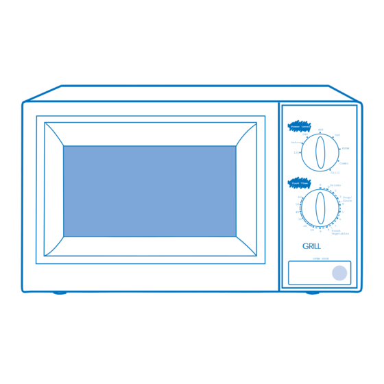
3. Operating Instructions 3-1 Control Panel Power Level DFROST REHEAT Defrost 800W Combi Grill Cook Time Drinks Soup/ INSTANT COOK Sauce Fresh Vegetables OPEN DOOR... -
Page 6: Checking That Your Oven Is Operating Correctly
Operating Instruction 3-2 Features & External Views Ventilation Holes Heater Light Door Safety Interlock Holes Power Level Defrost 800W Combi Grill Control Panel Cook Time Drinks Soup/ Sauce Door Latches Fresh Vegetables OPEN DOOR Open Door Push Button Glass Plate Guide Ring Metal Rack Power Level... -
Page 7: Variable Power Cooking Chart
Operating Instruction 3-4 Variable Power Cooking Chart OUTPUT POWER LEVEL GRILL HIGH 100% 800W MEDIUM HIGH 560W MEDIUM 400W LOW WEDIUM 240W DEFROST 160W 120W GRILL 1000W 3-5 Adjusting the Cooking Time During Cooking Stopping the Cooking Adding Extra Time To stop the cooking.. -
Page 8: Disassembly And Reassembly
4. Disassembly & Reassembly 4-1 Replacement of Magnetron, Motor Assembly and Lamp Remove the magnetron including the shield case, permanent magnet, choke coils andF capacitors Thermo S/W Lamp (all of which are contained in one assembly). Fan Motor 1. Disconnect all lead wires from the magnetron and lamp. - Page 9 Disassembly & Reassembly 4-3 Replacement of Door Assembly 4-3-1 Removal of Door Assembly Remove hex bolts securing the upper hinge and Hinge Upper lower hinge. Then remove the door assembly. Screw Hinge Lower 4-3-2 Removal of Door "C" Insert flat screwdriver into the gap between Door "E"...
- Page 10 Disassembly &ReaAssembly 4-3-5 Reassembly Test After replacement of the defective component parts of the door, reassemble it and follow the instructions below for proper installation and adjustment so as to prevent an excessive microwave leakage. 1. When mounting the door to the oven, be sure to adjust the door parallel to the bottom line of the oven face plate by moving the upper hinge and lower hinge in the direction necessary for proper alignment.
-
Page 11: Alignment And Adjustments
5. Alignment and Adjustments PRECAUTION 1. High voltage is present at the high voltage terminal of the high voltage transformer during any cook cycle. 2. It is neither necessary nor advisable to attempt measurement of the high voltage. 3. Before touching any oven components, or wiring, always unplug the oven from its power source and discharge the high voltage capacitor. -
Page 12: High Voltage Capacitor
Alignment and Adjustments 5-3 High Voltage Capacitor 1. Check continuity of the capacitor with meter set at the highest ohm scale. 2. Once the capacitor is charged, a normal capacitor shows continuity for a short time, and then indicates 9MΩ. 3. -
Page 13: Output Power Of Magnetron
Alignment and Adjustments 5-6 Output Power of Magnetron CAUTION MICROWAVE RADIATION PERSONNEL SHOULD NOT ALLOW EXPOSWRE TO MICROWAVE RADIATION FROM MICROWAVE GENERATOR OR OTHER PARTS CONDUCTING MICROWAVE ENERGY. The output power of the magnetron can be measured by performing a water temperature rise test. Equipment needed * Two 1-liter cylindrical borosilicate glass vessel (Outside diameter of 190mm) * One glass thermometer with mercury column... -
Page 14: Procedure For Measurement Of Microwave Energy Leakage
Alignment and Adjustments 5-8 Procedure for Measurement of Microwave Energy Leakage 1) Pour 275±15cc of 20±5ûC(68±9ûF) water in a beaker which is graduated to 600cc, and place the beaker in the center of the oven. 2) Start to operate the oven and measure the leakage Power Level by using a microwave energy survey meter. -
Page 15: Troubleshooting
6. Troubleshooting WARNING FOR HIGH VOLTAGE 4000 VOLTS EXIST AT THE HIGH VOLTAGE AREA. DO NOT OPERATE THE OVEN WITH CABINET PARTS REMOVED. DO NOT REMOVE THE CABINET PARTS IF THE POWER SUPPLY CORD IS PLUGGED IN THE WALL OUTLET. UNPLUG THE POWER CORD BEFORE SERVICING. - Page 16 Troubleshooting 6-1 Electrical Malfunction (Continved) Parts Cause Diagnosis Remedy 1) Too small If a small amount of food is heated for a long time, To increase the oven a load period of microwave may turn off during operation. load, add a glass of Microwave water into the oven.
-
Page 17: Unsatisfactory Cooking
Troubleshooting 6-2 Unsatisfactory Cooking Parts Cause Diagnosis Remedy 1) Open cathode Check the terminals with a multimeter to see Replace magnetron. of magnetron if the heater circuit is open. 2) Defective Check the H. V. Diode for continuity in the reverse and Replace H. -
Page 18: Exploded Views And Parts List
7. Exploded Views and Parts List 7-1 Main Exploded View... -
Page 19: Main Parts List
Parts No. Description/Specification Q'ty Remarks DE74-20017A TRAY-COOKING;GLASS(NEOREX/RE-31),T6,OD288 DE92-90441B ASSY-GUIDE ROLLER;G645C,D16.5 DE70-30116B PANEL-OUTER;SECC,T0.6,W351.7,L1014.7,WHT-C DE61-80005A HINGE-UPPER;SCP1,T2.3,ZN-COATIN,M745 DE61-80004A HINGE-LOWER;SCP1,T2.3,ZN-COATING,M745 DE92-40170S ASSY DOOR;M263G(G633C),WHT,CURRY DE39-40749A WIRE HARNESS-A;230V50Hz,M263G,MATSUI DE93-30365J ASSY CONTROL-BOX;M263G(G633C),CURRY DE66-90013A LEVER-DOOR;POM(F20-01),NTR,MW5630T M 10 DE93-20001A ASSY BODY LATCH;2ND-W1,M97G45/M9745 M 12 DE71-60010A COVER-AIR;PP(TB53),T1.7,WHT,64G,M745 M 13 DE67-60002A COUPLER;PPS,5GR,BRN,M97G45... - Page 20 DE64-10122C KNOB;ABS-HR0370,5g,WHT,PMS3272C(GRN DE72-70165J CONTROL-PANEL;ABS,WHT(W9501),-,-,M263G(G633C DE45-10075A TIMER-ASSY;TMFF60MTN1,220/240V,240-GRILL- 3501-000309 RELAY-POWER;240V,3750VA,15A,-,6mS,20mS DE39-40545A WIRE HARNESS-B;230V50HZ,G635C DE93-30586A ASSY CONTROL-PANEL;240V50Hz,M263G,PURE-WHT,CURRY 7-5 Assembly Body Latch Parts List Ref. No Parts No. Description / Specification Q'ty Remarks DE66-90001A LEVER-SWITCH;P.O.M(F20-02) 2 6 NTR 2ND-W 3405-000178 SWITCH-MICRO;250V,15A, 200gf, SPST-NO 3405-000175 SWITCH-MICRO;250V,15A, 200gf, SPST-NO...
-
Page 21: Standard Parts List
Exploded Views and Parts List 7-6 Standard Parts List Parts No. Description / Specification Q'ty Remarks DE60-10012A SCREW-TAP TITE;TH,+,3,M4,L10,SWR10,ZPC2,TOOTH N/FILTER DE60-10012A SCREW-TAP TITE;TH,+,3,M4,L10,SWR10,ZPC2,TOOTH P-C-EA” DE60-10059A SCREW-TAP TH;TH,M4,L8,SUS410,CR B/HEAT DE60-10080A SCREW-WASHER;M5,L12,2S DE60-10080A SCREW-WASHER;M5,L12,2S DE60-10082H SCREW-A;2S-4X12,TOOTHED B-PLTE DE60-10082H SCREW-A;2S-4X12,TOOTHED B/UPP DE60-10082H SCREW-A;2S-4X12,TOOTHED BD-LAT DE60-10082H SCREW-A;2S-4X12,TOOTHED... -
Page 22: Schematic Diagram
8. Schematic Diagram Wiring Diagram ASSY CHOKE P.C.B TIMER INRUSH CAVITY SECONDARY S/W SWITCH RELAY H.V.T RESISTOR H.V.D 230V~ 50Hz H.V.FUSE (0.75A) 230V H.V.C (0.95uF) MONITOR SWITCH COIL S/W2 S/W1 PRIMARY S/W3 SWITCH NOTE FUNCTION ROTARY MAGNETRON DOOR IS OPEND SYMBOL COLOR BROWN...
Need help?
Do you have a question about the M263G and is the answer not in the manual?
Questions and answers