Table of Contents
Advertisement
Quick Links
ICC
INDUSTRIAL CONTROL COMMUNICATIONS, INC.
Multiprotocol Wireless
Thank you for purchasing the OPC-E1-WiE Multiprotocol Wireless Ethernet Interface.
•
This product is designed to connect the FRENIC-Multi series of inverters to wireless Ethernet
communication networks. Please read this instruction manual thoroughly in order to become
familiar with the proper interface handling, installation and usage procedures.
•
Improper handling may inhibit correct operation or cause premature interface failure.
•
Please deliver this instruction manual to the end user of the interface, and retain it in an
accessible location.
•
For inverter usage instructions, please refer to the applicable FRENIC-Multi inverter instruction
manual.
September 2011
ICC #10719-1.100-000
OPC-E1-WiE
Ethernet Interface
Instruction Manual
© 2011 Industrial Control Communications, Inc.
Advertisement
Table of Contents
Troubleshooting

Summary of Contents for ICC OPC-E1-WiE
- Page 1 OPC-E1-WiE Multiprotocol Wireless Ethernet Interface Thank you for purchasing the OPC-E1-WiE Multiprotocol Wireless Ethernet Interface. • This product is designed to connect the FRENIC-Multi series of inverters to wireless Ethernet communication networks. Please read this instruction manual thoroughly in order to become familiar with the proper interface handling, installation and usage procedures.
- Page 2 OPC-E1-WiE Multiprotocol Wireless Ethernet Interface Instruction Manual Part Number 10719-1.100-000 Printed in U.S.A. ©2011 Industrial Control Communications, Inc. All rights reserved Industrial Control Communications, Inc. reserves the right to make changes and improvements to its products without providing notice. Notice to Users INDUSTRIAL CONTROL COMMUNICATIONS, INC.’S PRODUCTS ARE NOT AUTHORIZED FOR USE...
-
Page 3: Safety Precautions
Preface Thank you for purchasing the OPC-E1-WiE Multiprotocol Wireless Ethernet Interface. This instruction manual has been prepared to help you connect your FRENIC-Multi inverter to a variety of wireless Ethernet control networks. This instruction manual does not contain inverter usage instructions. Please refer to this instruction manual in conjunction with the FRENIC-Multi Instruction Manual (INR-SI47-1094-E) in order to become familiar with the proper handling, installation and operation of this product. - Page 4 Installation and wiring • To avoid electrical shock, remove all power from the inverter and wait at least five minutes prior to starting installation. Additionally, confirm that the DC link bus voltage as measured between the P (+) and N (-) terminals is less than 25 VDC. •...
- Page 5 Maintenance, inspection, and parts replacement • To avoid electrical shock, remove all power from the inverter and wait at least five minutes prior to starting inspection. Additionally, confirm that the DC link bus voltage as measured between the P (+) and N (-) terminals is less than 25 VDC. •...
-
Page 6: Table Of Contents
− TABLE OF CONTENTS − PRE-OPERATION INSTRUCTIONS ............. 8 Product Overview ....................8 Unpacking and Product Confirmation ..............10 1.2.1 Shipment Confirmation ..................... 10 1.2.2 Component Overview....................... 11 LED Indicators ....................... - Page 7 5.6.3 Submitting Changes ......................33 Config Tab......................34 5.7.1 Information Window ......................34 5.7.2 Authentication Configuration .................... 34 5.7.3 IP Address Configuration ....................35 5.7.4 MAC Address Configuration ..................... 35 ...
-
Page 8: Troubleshooting
8.2.3 ControlLogix Examples: Setup ..................68 8.2.4 ControlLogix Example: I/O Messaging ................69 8.2.5 ControlLogix Example: Generic Default I/O Add-On Instruction ........72 8.2.6 ControlLogix Example: AC/DC Drive Profile Add-On Instruction ........74 ... -
Page 9: Pre-Operation Instructions
SMA connector. The antenna can be rotated 360 degrees at its connection point and from 0 to 90 degrees at its knuckle. An optional desktop/magnetic base antenna (ICC part #10693) and 30cm antenna extension cable (ICC part #10694) are also available. Refer to section 2.4. - Page 10 Network Timeout Action A configurable network timeout action can be programmed that allows registers to have their own unique "fail-safe" conditions in the event of a network interruption. Refer to section 5.7.6. Field-Upgradeable As new firmware becomes available, the interface can be upgraded in the field by the end-user. Refer to section 7.6 for more information.
-
Page 11: Unpacking And Product Confirmation
Check the enclosed items. Confirm that the correct quantity of each item was received, and that no damage occurred during shipment. • OPC-E1-WiE interface board (with antenna) in enclosure (see Figure 1). • One option retaining screw (see Figure 2). -
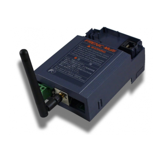
Page 12: Component Overview
Network status LED Module status LED Antenna jack Figure 4: OPC-E1-WiE Component Overview Power Supply Terminal Block The power supply terminal block can be used to provide power (7-24VDC) to the interface card. Refer to section 2.3. Network Status and Module Status LEDs These LEDs indicate the current status of the interface card and protocols in use. -
Page 13: Led Indicators
EtherNet/IP (link integrity) has been established specification, Volume 2, Chapter 9. between the interface card and an • Contact ICC technical support if a access point (infrastructure mode.) blinking red error code is observed. • Blinks slowly whenever the interface card is in ad hoc mode. -
Page 14: Environmental Specifications
1.4 Environmental Specifications The interface’s environmental specifications are detailed in Table 1. Table 1: Environmental Specifications Item Specification Indoors, less than 1000m above sea level, do not expose to direct Operating Environment sunlight or corrosive / explosive gasses -10 ∼ +50°C (+14 ∼ +122°F) Operating Temperature -40 ∼... -
Page 15: Installation
2 INSTALLATION 2.1 Pre-Installation Instructions • To avoid electrical shock, remove all power from the inverter and wait at least five minutes prior to starting installation. Additionally, confirm that the DC link bus voltage as measured between the P (+) and N (-) terminals is less than 25 VDC. •... -
Page 16: Installation Procedure
2.2 Installation Procedure Before installing the interface card, perform all wiring for the main circuit terminals and control circuit terminals. Remove the terminal cover from the inverter. Note: For inverters with a capacity of 5.5 to 15 kW, the terminal cover retaining screw must first be removed in order to remove the terminal cover. - Page 17 Mount the interface card on the inverter, aligning the male RJ45 connector on the back side of the interface card with the now-vacant keypad RJ45 connector on the inverter. Ensure that the interface card is fully seated on the inverter, and that its plastic enclosure is sitting squarely on the inverter’s terminal cover.
- Page 18 Grasping the bottom of the interface card enclosure cover, gently pull it away from the inverter to remove it and expose the interface card PCB. Attach the free end of the option connection cable to the connector labeled CN1 on the interface card PCB.
-
Page 19: Power Supply
2.3 Power Supply Power for the interface card must be externally supplied: it is not automatically drawn from the inverter. A 3-position pluggable terminal block is provided in the lower-left portion of the interface board for connecting an external 7-24VDC power supply. •... -
Page 20: Antenna Options
Table 4 lists the recommended wire size, terminal screw size and tightening torque when connecting wires to TB1. Additionally, Figure 10 indicates the recommended amount of insulation that should be stripped from the wire prior to inserting it into TB1. Table 4: TB1 Wiring Specifications Wire Size Terminal Screw Size... -
Page 21: Optional #10694 Antenna Extension Cable
2.4.2 Optional #10694 Antenna Extension Cable ICC part #10694 is a 30cm-long antenna extension cable (refer to Figure 12). The #10694 antenna extension cable can be used with the optional #10693 desktop antenna (refer to section 2.4.3), but it is most commonly applied in conjunction with the standard dipole antenna (refer to section 2.4.1.) For this... -
Page 22: Initial Wireless Settings
2.5 Initial Wireless Settings In order to initially connect to a wireless device, the network’s wireless access point or router must be configured such that it is compatible with the interface card’s initial wireless settings. While these settings can be changed after initial connection, the interface card’s factory-default wireless settings are: SSID ........ -
Page 23: Inverter Function Code Settings
3 INVERTER FUNCTION CODE SETTINGS The inverter function codes listed in Table 5 are critical for overall operation of the end-to-end communication system. Some of these function codes must be set to specific values, and some may have multiple allowable settings depending on the desired operation of the overall application. Although there may be many other function codes that will require configuration for your specific application, it is important to understand the manner in which the following function codes will impact successful communications with, and control of, the inverter. - Page 24 inverter (the transmission of request packets) is performed asynchronously to other threads in the interface card’s internal operating system. Some of these other threads are able to reboot the interface card under certain circumstances (when commanded by the user via the Finder program, or after configuration changes are submitted via the web browser, for example).
-
Page 25: Inverter Control-Related Settings
RS-485 Protocol Selection (y20) Determines the RS-485 port protocol, and must be set to a value of “0” (Modbus RTU). 3.2 Inverter Control-Related Settings The following function codes relate to whether or not the inverter is to be controlled (command word and/or frequency command) from the network, or whether the inverter will be locally-controlled, and only monitored and/or configured via the network. -
Page 26: Finder Application
4 FINDER APPLICATION 4.1 Overview The “ICC Finder” application is a simple Windows PC program (just a single .exe file, no installations, DLL’s etc.), which when executed discovers all ICC communication interfaces on the current Ethernet subnet, regardless of whether or not their network parameters are currently compatible with the subnet upon which they reside. -
Page 27: Configuring The Ip Address
IP address. The interface comes from the factory configured to obtain an IP address dynamically (DHCP/BOOTP). You can determine the interface’s current IP address using the ICC Finder application included on the CD provided with the interface, or available from the ICC website at http://www.iccdesigns.com. -
Page 28: Embedded Web Server
5 EMBEDDED WEB SERVER 5.1 Overview The interface contains an embedded web server (also known as an HTTP server), which allows users to access the inverter’s internal data in a graphical manner with web browsers such as Microsoft Internet Explorer or Mozilla Firefox. In this way, the inverter can be monitored, configured and controlled from across the room or from across the globe. -
Page 29: Authentication
Refer to Figure 19. The factory-default user name is “root”, and the password is “icc”. Note that the username and password are case-sensitive, and that once authenticated, the authentication will remain in effect from that point until all browser windows are closed. -
Page 30: Function Code Group Selection List
5.4.2 Function Code Group Selection List The Function Code Group Selection List is located in the upper-left hand corner of the Monitor Tab. Refer to Figure 22. Individual groups can be selected by clicking on the group name. Multiple groups may also be selected by holding down the CTRL key while clicking on the group names, or... -
Page 31: Function Code List Filter
Figure 23: Function Code List Some items to keep in mind when interacting with the Function Code List are: • When entering new function code values, be sure that the number being entered is appropriate for the currently-selected radix (refer to section 5.4.6): for example, an entered value of “1000” in hexadecimal is equal to 4096 in decimal. -
Page 32: Non-Scanned Function Code Refresh
For example, to turn on bit #10 in the inverter’s operation command word, enter the hexadecimal number 0400. 5.5 PROFINET Tab PROFINET is not currently supported on the OPC-E1-WiE. -
Page 33: Bacnet Tab
5.6 BACnet Tab The BACnet tab provides for the configuration of the device on a BACnet/IP network. Refer to Figure Figure 27: BACnet Tab 5.6.1 Information Window Figure 28 shows the Information Window, which is located in the upper- right hand corner of the BACnet tab. This window displays various informational messages regarding the status of the BACnet configuration... -
Page 34: Submitting Changes
5.6.3 Submitting Changes Whenever either of the BACnet configuration elements (Device Name or Device ID) has been changed, the “submit” button located in the left-hand portion of the web page must be clicked in order to write these settings to the interface card’s filesystem. -
Page 35: Config Tab
FTP Figure 33: Authentication Configuration session is initiated, or when a configuration change is performed via the Finder utility. Contact ICC for assistance if you have forgotten your customized credentials. -
Page 36: Ip Address Configuration
Figure 35 shows the entry boxes that are used to view and/or modify the unique MAC address of the interface. The MAC address should not be changed without first consulting ICC Technical Support. Figure 35: MAC Address Configuration 5.7.5 Wireless Settings... -
Page 37: Timeout Configuration
Authentication: The interface supports five different types of authentication: NONE, WEP, WPA, WPA2 and AUTO. The default setting is AUTO. NONE may be chosen if wireless security is not desired. WEP (Wired Equivalency Privacy) and WPA/WPA2 (Wi-Fi Protected Access) offer different levels of security for wireless communication. -
Page 38: Submitting Changes
If timeout/failsafe processing is not desired, just set the “register” fields for all indexes to 0 (disabled). This is the default condition. “DEC” and “HEX” selection buttons are also available, and allow changing the “value” column data display and entry radix between decimal and hexadecimal formats, respectively. These buttons provide the ability to interact with the various inverter registers in their most natural radix (e.g. -
Page 39: Ethernet/Ip Tab
5.8 EtherNet/IP Tab The EtherNet/IP tab provides access to configuration items related to communication on an EtherNet/IP network. Refer to Figure 39. Figure 39: EtherNet/IP Tab 5.8.1 Information Window Figure 40 shows the Information Window, which is located in the upper-right hand corner of the EtherNet/IP tab. -
Page 40: Run/Idle Flag Behavior
5.8.3 Run/Idle Flag Behavior EtherNet/IP clients (such as PLCs) have the option of adding a 32-bit “run/idle” header to all class 1 (I/O) data packets sent to devices. Bit 0 of this header is called the “run/idle flag” by the EtherNet/IP specification, and is intended to signify Figure 42: Run/Idle Flag Behavior Selection when the client is in a “running”... -
Page 41: Submitting Changes
may request larger consumed and/or produced data sizes, but all unreferenced consumed data will be ignored, and all unreferenced produced data will contain dummy “0” values). The first word (two bytes) of consumed data will be written to register 1799 (operation command register) and the second word will be written to register 1798 (frequency command). -
Page 42: Alarm Tab
5.9 Alarm Tab The Alarm tab provides a configurable mechanism by which the interface card can autonomously monitor any available inverter register and send emails to up to four recipients when a certain condition is detected. The alarm conditions have both value and time constraints, and can be configured to retrigger at a fixed interval as long as the alarm condition continues to be satisfied. -
Page 43: Email Configuration
5.9.2 Email Configuration In order for an alarm trigger to successfully send a notification email, some network settings must first be configured properly (refer to Figure 47 and Figure 48.) DNS Servers: Enter the dotted-decimal IP addresses of the primary and secondary DNS servers which will be used to resolve the configured SMTP server name. -
Page 44: Alarm Configuration
5.9.3 Alarm Configuration The interface supports twenty independently-configurable alarms. As shown in Figure 51, each alarm has a variety of configuration elements, which will be explained further below. Figure 51: Alarm Configuration Box Alarm Selection: This drop-down box allows the selection of one of the twenty available alarms. When an alarm is selected, that alarm’s current configuration parameters will be populated in the alarm configuration box. -
Page 45: Submitting Changes
a maximum of the indicated number of times. If at any time during the subsequent transmissions the alarm condition is evaluated as “false”, then the alarm will be reset and email transmissions for this alarm will stop (until the next time the alarm is triggered, of course). Subject: Enter a string of up to 128 characters in length which will appear in the “subject”... -
Page 46: Modbus Tab
Before enabling this timer, therefore, it is suggested that users read the ICC whitepaper titled “A Discussion of Modbus/TCP Server-Side Timeout Processing”, which can be found in the documents section at Figure 55: Supervisory Timer Selection http://www.iccdesigns.com. -
Page 47: Register Remap Configuration
5.10.3 Register Remap Configuration At times, it may be convenient to access inverter registers in bulk Modbus transactions. This may be especially true in situations where it is desired to access certain registers that are natively non- contiguous. For example, if it were desired to read the inverter’s operating frequency (register 2058), DC link bus voltage (register 2070), and operation status (register 2063), this could be accomplished in two different ways: Implement three separate Modbus read transactions, each one reading one register only, or... -
Page 48: Submitting Changes
5.10.4 Submitting Changes Whenever the Modbus configuration has been changed, the “submit” button located on the right- hand portion of the web page must be clicked in order to write these settings to the interface card’s filesystem. Refer to Figure 57. Note that because these configuration elements are read from the filesystem only when the interface card boots up, the act of submitting configuration... -
Page 49: Dashboard Tab
5.11 Dashboard Tab The Dashboard Tab provides access to a virtual keypad, as well as a variety of gauges, meters and graphs that can be configured to provide an at-a-glance graphical overview of critical application variables in real-time. A total of 10 gauge windows are available (two at a time), and each gauge window can be configured to display any scanned register’s value via one of six different gauge types. -
Page 50: Virtual Keypad
5.11.2 Virtual Keypad A “virtual keypad” is displayed on the left-hand side of the dashboard tab, and acts as an interface for several useful pieces of control and monitor information. For an overview of the virtual keypad interface, refer to Figure 60. Note that it is recommended to suspend all external protocol-based communications with PLC’s, etc. -
Page 51: Gauge Window Navigation
• REV: sets bit #1 (“REV”) and clears bit #0 (“FWD”) in the operation command word (register 1799). • STOP: clears both bit #0 (“FWD”) and bit #1 (“REV”) in the operation command word (register 1799). • RESET: writes a value of “1” to register 1807, which corresponds to inverter function code S14 (alarm reset command). - Page 52 Max Value: The gauge’s maximum indicated value. Similar to the Min Value attribute, negative values can be used if desired. Indicated value characteristics can even be inverted by setting the Max Value attribute to a value less than the Min Value attribute. Update Button: Clicking the update button will apply the current configuration attribute settings to the gauge.
- Page 53 Pos/Neg Meter: Refer to Figure 66. Similar to the “meter” gauge, this type of meter also implements a common panel meter-type display format, but in this instance the indicated value can be positive or negative (two’s complement interpretation). In other words, raw register values of 0..0x7FFF equate to 0..32767 , and values of 0x8000..0xFFFF equate to -32768..-1.
-
Page 54: Submitting Changes
At times, it may be convenient to zoom in on a particular gauge or meter in order to more clearly see the indicator, or to fill the computer screen with a particular gauge’s image. This can be easily accomplished with the web browser’s Flash Player plug-in by right- clicking on the gauge and selecting the desired zoom level (refer to Figure 69). -
Page 55: Function Code Numbering And Behavior
6 FUNCTION CODE NUMBERING AND BEHAVIOR 6.1 Register Numbers All accessible inverter function codes are referenced by their Modbus register indexes, as defined in the RS-485 User’s Manual (MEH448), section 3 (Table 3.2). These same register numbers are used when accessing and configuring function codes via an Ethernet protocol. -
Page 56: Scanned And Non-Scanned Registers
Table 6: Function Code-to-Register Conversion Function Code Group Group Example Number Code Name Fundamental F07 (acceleration time 1): (0 x 256) + 7 + 1 = 8 Functions Extension Terminal E98 (terminal [FWD] function): (1 x 256) + 98 + 1 = 355 Functions Control Functions C20 (jogging frequency): (2 x 256) + 20 + 1 = 533... - Page 57 inverter. If the value was not accepted by the inverter, then the unsuccessful write can be observed by reading the current (unchanged) value of the register during a subsequent network transaction. If the unsuccessful write was initiated via the web browser’s monitor tab, then the displayed register will revert back to its original value automatically.
-
Page 58: Filesystem & Firmware
7 FILESYSTEM & FIRMWARE 7.1 Overview The interface card’s on-board filesystem is used to store files for use by the application firmware. Currently, the application firmware’s main use of the filesystem is to store XML-encoded configuration files that dictate the characteristics of the various protocols. Each protocol that requires configuration will have its own XML file stored on the filesystem. -
Page 59: Initiating Ftp Via The Finder Utility
(refer to Figure 71.) Enter the currently-configured user name and case-sensitive password (defaults are “root” and “icc”, respectively), then click “Log On.” The web browser will then display the filesystem’s contents (refer to Figure 72.) FTP access via a web... - Page 60 Figure 74: FTP Navigation with Windows Explorer You will then be presented with an authentication dialog (refer to Figure 75.) The user name will already be filled-in. Enter the case-sensitive password (default is “icc”) and click “Log On.” Figure 75: FTP Authentication Windows Explorer will then display the filesystem’s contents (refer to Figure 76.) You can now perform...
-
Page 61: Using Ftp With A Windows Command Prompt
The FTP client will connect to the unit and then prompt for the username and case-sensitive password (defaults are “root” and “icc”, respectively). Upon successful entry of the authentication information, you will be presented with an “ftp>”... -
Page 62: Using Ftp With Core Ftp Le
“File…connect”. Click on the “New Site” button, then enter a Site Name, IP Address, username (default is “root”) and case-sensitive password (default is “icc”). The “Port”, “Timeout”, and “Retries” fields should already contain the default values. Click the “Connect” button Figure 81: Core FTP Site Manager when done. -
Page 63: Loading New Application Firmware
ICC is continually striving to enhance the functionality and flexibility of our products, and we therefore periodically release new embedded firmware to achieve these goals and meet customer requests. Flash firmware files and all related documentation (such as updated user manuals) can be downloaded from http://www.iccdesigns.com. -
Page 64: Protocol-Specific Information
8 PROTOCOL-SPECIFIC INFORMATION This section will discuss topics that are specific to each of the supported protocols. 8.1 Modbus/TCP 8.1.1 Overview The interface card supports Schneider Electric’s Modbus/TCP protocol, release 1.0. The interface is conformance class 0 and partial class 1 and class 2 compliant, and allows up to 8 simultaneous Modbus/TCP client connections (sockets). -
Page 65: Coil & Discrete Input Mappings
8.1.2 Coil & Discrete Input Mappings The Modbus/TCP driver provides read/write support for coils (0X references) and read-only support for discrete inputs (1X references). These will collectively be referred to from here on out as simply “discretes”. Accessing discretes does not reference any new physical data: discretes are simply indexes into various bits of existing registers. -
Page 66: Ethernet/Ip
The interface card supports the EtherNet/IP protocol, as administered by the Open DeviceNet Vendor Association (ODVA). • This product has been self-tested by ICC, Inc. and found to comply with ODVA EtherNet/IP Conformance Test Software Version A-5. • I/O connection sizes for assembly instances 100 and 150 are adjustable between 0 and 64 bytes (32 registers max @ 2 bytes per register = 64 bytes). -
Page 67: Odva Ac/Dc Drive Profile
8.2.2 ODVA AC/DC Drive Profile The interface card supports the ODVA AC/DC drive profile. No special EtherNet/IP configuration of the interface card is required when using the AC/DC drive profile: all that is needed is that the controller must target either assembly instances 20 & 70 or 21 & 71 in its connection parameters. The AC/DC drive profile implementation provides support for several required CIP objects, which are specified in Table 8. - Page 68 NetRef: Not used (value is ignored). Speed Reference: Inverter speed reference in RPM. Maps to inverter register 1798 (function code S05 / frequency command). The speed reference component of the AC/DC drive profile output instances is always in units of RPM. Therefore, the interface card applies the RPM-to-Hz conversion indicated in Equation 5 in order to determine the appropriate frequency command value (in units of Hz) to be written to register 1798.
-
Page 69: Controllogix Examples: Setup
Drive State: Indicates the current state of the Control Supervisor Object state machine. Refer to the ODVA EtherNet/IP specification (object library) for detailed information on the Control Supervisor Object state machine. Speed Actual: Inverter operating speed in RPM. Maps to inverter register 2058 (function code M09 / output frequency). -
Page 70: Controllogix Example: I/O Messaging
Switch to online mode. Right click on the 1756-ENBT/A module in the I/O Configuration and choose “Properties”. Select the Port Configuration tab from the Module Properties dialog box. Confirm that the IP Address, Subnet Mask and Gateway Address fields are configured correctly. The IP Address must match the IP Address entered when the new module was first created. - Page 71 Right click on the 1756-ENBT/A node under the I/O Configuration in the controller organizer view and choose “New Module…” Choose “Generic Ethernet Module” in the Select Module dialog box and click “OK”. Refer to Figure 86. Figure 86: Adding a New Generic Ethernet Module The module properties dialog box will open (refer to Figure 87).
- Page 72 Output: The Output Assembly is the collection of command & configuration data that is sent as an output from the PLC and consumed by the interface card. Its structure is defined by the Consumed Register Configuration as described in section 5.8.4. The Output Assembly Instance must be set to 100 when connecting to the vendor-specific I/O assembly instances (or 20/21 when using the ODVA AC/DC drive profile), and the size must be set to the number of 16-bit registers that we wish to send to the interface card.
-
Page 73: Controllogix Example: Generic Default I/O Add-On Instruction
We can directly interact with these tags in order to control and monitor the inverter. In Figure 91, for example, we can see that the first 16-bit word of output data (Fuji_Inverter:O.Data[0]) has been set to a hexadecimal value of 0x0001. Referring back to Figure 43, we can see that the first element of the consumed register configuration references register 1799, which is the inverter’s operation command register. - Page 74 Figure 93: Create Generic Default AOI Tags Double click “MainRoutine” under Tasks …MainTask …MainProgram in the controller organizer view. Right click on the first ladder logic rung in the MainRoutine window and select “Add Ladder Element...” The “Add Ladder Element” window appears. Select the generic default I/O AOI in the Add-On folder.
-
Page 75: Controllogix Example: Ac/Dc Drive Profile Add-On Instruction
Figure 95: Configure Generic Default AOI The program is now complete. Save, download and run the program. 8.2.6 ControlLogix Example: AC/DC Drive Profile Add-On Instruction The AC/DC drive profile add-on instruction is a simple interface to command and monitor the inverter. It is based on the assembly instances 21 &... - Page 76 Figure 97: AC/DC Drive Profile AOI Double click “Controller Tags” in the controller organizer view and select the “Edit Tags” tab at the bottom. Create the tags in Figure 98. Figure 98: Create AC/DC Drive Profile AOI Tags Double click “MainRoutine” under Tasks …MainTask …MainProgram in the controller organizer view.
-
Page 77: Explicit Messaging Tag Reference
Edit the add-on instruction according to Figure 100. Figure 100: Configure AC/DC Drive Profile AOI The program is now complete. Save, download and run the program. 8.2.7 Explicit Messaging Tag Reference When class 3 (explicit messaging) connections are used, register contents are read from and written to the interface card via EtherNet/IP by reference to “tag names”. -
Page 78: Controllogix Explicit Messaging Example: Read A Register Block
(such as “rd_reg_2050[8]”, which starts at register 2050+8 = register 2058, the inverter’s output frequency register). In a similar manner, to write data to the interface card, the application PLC program must reference a “destination element” to which to start writing and the “number of elements” to write. Again, the “destination element”... - Page 79 Add a MSG instruction to the main program. Double click “MainRoutine” under Tasks …MainTask …MainProgram in the controller organizer view. Right click on the first ladder logic rung in the MainRoutine window and select “Add Ladder Element...” The “Add Ladder Element” window appears.
- Page 80 Figure 106: MSG Instruction Configuration “Configuration” tab settings: Change the “Message Type” to “CIP Data Table Read”. In the "Source Element” field, enter the read tag you wish to access (refer to section 8.2.5.) In this example, we will be reading a total of 21 registers beginning at rd_reg_2050 (function code M01 / per-unit frequency reference –...
- Page 81 after every transmission. For efficiency, it is recommended to enable “Cache Connections”. Figure 108: Setting the Communication Path Click “OK” to close the MSG Configuration dialog. At this stage, MainRoutine should look like Figure 109. Figure 109: MainRoutine Assign a tag to the XIO element. Double-click on the XIO element located to the left of the MSG block.
- Page 82 Figure 110: Configure XIO Element Figure 111: Complete Program Figure 112: Viewing the Register Values...
-
Page 83: Controllogix Explicit Messaging Example: Read A Single Register
8.2.9 ControlLogix Explicit Messaging Example: Read a Single Register The configuration and execution for reading a single register is in general identical to that required for reading a block of registers as detailed in section 8.2.8. The only difference is in the configuration of the MSG instruction. -
Page 84: Controllogix Explicit Messaging Example: Reading And Writing
8.2.11 ControlLogix Explicit Messaging Example: Reading and Writing Often times, applications may need to both read data from and write data to the inverter. At a minimum, this will require two MSG instructions and two message controller tags. Figure 115 shows an example of three MSG instructions, one for reading and two for writing (the inverter’s frequency command and operation command word). -
Page 85: Allen Bradley Csp
8.3 Allen Bradley CSP 8.3.1 Overview Ethernet-enabled Allen-Bradley legacy PLCs (such as the PLC5E and SLC-5/05 series) use a protocol called CSP (Client Server Protocol) to communicate over the Ethernet network. The flavor of CSP used by these PLCs is also known as “PCCC” (Programmable Controller Communication Commands) and “AB Ethernet”. - Page 86 Table 12: Examples of EtherNet/IP-Style Bulk Access via File N60 Start Target Register of Max Number of Offset/Element Configuration Array Accessible Elements The application PLC program uses a MSG instruction that is configured with a “Data Table Address” from which to start the access and a “Size in Elements” which determines the number of items to access (read or write).
-
Page 87: Slc-5/05 Example: Read A Register Block
8.3.3 SLC-5/05 Example: Read a Register Block This example program will show how to continuously read a block of registers from the inverter with a single MSG instruction. Only one read request is outstanding at any given time. Run RSLogix 500, and create a new configuration. - Page 88 Figure 119: MSG Instruction Selection Figure 120: XIO Instruction Selection Configure the MSG instruction. Set the “Read/Write” field to “Read”, “Target Device” field to “PLC5”, “Local/Remote” field to “Local”, and “Control Block” to “N20:0”. Upon hitting the <ENTER> key while in the “Control Block” entry box, the MSG Properties dialog box should appear (or it can be opened by clicking on the “Setup Screen”...
- Page 89 Figure 121: MSG Configuration, "General" Tab Figure 122: MSG Configuration, "MultiHop" Tab Figure 123: PLC Program after MSG Instruction Configuration...
-
Page 90: Slc-5/05 Example: Read A Single Register
Assign a tag to the XIO element. Double-click on the XIO element located to the left of the MSG block. Type in N20:0/15 (MSG instruction’s enable bit). This configuration causes the MSG instruction to automatically retrigger itself when it completes. While this is acceptable for the purposes of this example, it can produce high network utilization. -
Page 91: Slc-5/05 Example: Multiple Msg Instructions
Figure 126: Read the Inverter’s Output Frequency Register 8.3.5 SLC-5/05 Example: Multiple MSG Instructions At times, reading from different groups of registers may be necessary. For example, a specific application may require some registers located in various disjoint locations in the register map. To accomplish this task efficiently, multiple MSG instructions can be implemented in the PLC program. -
Page 92: Slc-5/05 Example: Reading And Writing
8.3.6 SLC-5/05 Example: Reading and Writing Often times, applications may need to both read data from and write data to the inverter. At a minimum, this will require two MSG instructions and two message control files. Figure 128 shows an example of two MSG instructions, one for reading and one for writing. -
Page 93: Bacnet/Ip
• The BACnet driver does not trigger timeout events (section 5.7.6). 8.4.1 Protocol Implementation Conformance Statement BACnet Protocol Date: June 1, 2011 Vendor Name: ICC, Inc. Product Name: Fuji Electric FRENIC-Multi Inverter Product Model Number: OPC-E1-WiE Applications Software Version: V1.100 Firmware Revision: V1.100... - Page 94 LonTalk, (Clause 11), medium: ______ Other: ______ Device Address Binding: Is static device binding supported? (This is currently for two-way communication with MS/TP slaves and certain other devise.) Networking Options: Router, Clause 6 - List all routing configurations Annex H, BACnet Tunneling Router over IP BACnet/IP Broadcast Management Device (BBMD) Does the BBMD support registrations by Foreign Devices? Character Sets Supported:...
- Page 95 Object Types/Property Support Table Table 13: BACnet Object Types /Properties Supported Object Type Property Binary Binary Analog Analog Device Input Output Input Output Object Identifier Object Name Object Type System Status Vendor Name Vendor Identifier Model Name Firmware Revision Appl Software Revision Protocol Version Protocol Revision Services Supported...
-
Page 96: Supported Objects
8.4.2 Supported Objects Table 14: Binary Input Object Instance Summary Active/ Instance ID Object Name Description Inactive Text FWD_ROT_STATUS Forward rotation status forward/off REV_ROT_STATUS Reverse rotation status reverse/off EXT_STATUS DC injection braking braking/off INVERTER_SHUTDOWN Inverter shutdown on/off BRAKING Braking braking /off DC bus voltage normal on/off TORQUE_LIMITING... - Page 97 Table 15: Binary Output Object Instance Summary Active/ Instance ID Object Name Description Inactive Text FWD_ROT_CMD Forward rotation command forward/off REV_ROT_CMD Reverse rotation command reverse/off General purpose input on/off General purpose input on/off General purpose input on/off General purpose input on/off General purpose input on/off...
-
Page 98: Supported Object Details
8.4.3 Supported Object Details Binary Input Objects BI1 ..Indicates whether the inverter is running forward. Corresponds to function code M14, bit 0. BI2 ..Indicates whether the inverter is running reverse. Corresponds to function code M14, bit 1. BI3 ..Indicates DC injection braking or pre-exciting. Corresponds to function code M14, bit 2. BI4 .. -
Page 99: Troubleshooting
“MODULE STATUS” LED is flashing red with an “x-y-z” 3- Firmware- blink sequence. The Contact ICC for further assistance. generated error number of LED flashes indicates an error code. Message on a web... - Page 100 REVISIONS Date Manual Number Details April 2009 10719-1.000-000 Preliminary release May 2009 10719-1.000-000 Official V1.000 firmware release March 2010 10719-1.000-001 Minor corrections September 2011 10719-1.100-000 Minor driver updates...
- Page 101 INDUSTRIAL CONTROL COMMUNICATIONS, INC. 1600 Aspen Commons, Suite 210 Middleton, WI USA 53562-4720 Tel: [608] 831-1255 Fax: [608] 831-2045 http://www.iccdesigns.com Printed in U.S.A...
Need help?
Do you have a question about the OPC-E1-WiE and is the answer not in the manual?
Questions and answers