Table of Contents
Advertisement
Advertisement
Table of Contents

Summary of Contents for MTU 12V4000S83
- Page 1 Operating Instructions Diesel engine 12 V 4000 S83 16 V 4000 S83 MS150026/02E...
- Page 2 This Publication is protected by copyright and may not be used in any way whether in whole or in part without the prior written permission of MTU Friedrichshafen GmbH. This restriction also applies to copyright, distribution, translation, mi- crofilming and storage or processing on electronic systems including data bases and online services.
-
Page 3: Table Of Contents
Table of Contents 1 Safety 7 Task Description 1.1 Important provisions for all products 7.1 Engine 1.2 Personnel and organizational requirements 7.1.1 Engine – Performing test run 7.1.2 Engine – Barring manually 1.3 Transport 7.1.3 Engine – Barring with starting system 1.4 Crankshaft transport locking device 1.5 Safety regulations for startup and operation 7.2 Cylinder Liner... - Page 4 7.15.5 Charge-air coolant pump – Relief bore check 8 Appendix A 7.16 Belt Drive 8.1 Abbreviations 7.16.1 Drive belt – Condition check 8.2 MTU contact persons/service partners 7.17 Battery-Charging Generator 7.17.1 Battery-charging generator ‒ Check 9 Appendix B 7.17.2 Battery-charging generator drive – Drive belt tension adjustment 9.1 Special Tools...
-
Page 5: Safety
• With fluids and lubricants approved by the manufacturer in accordance with the (→ Fluids and Lubri- cants Specifications of the manufacturer) • With spare parts approved by the manufacturer in accordance with the (→ Spare Parts Catalog/MTU contact/Service partner) •... -
Page 6: Personnel And Organizational Requirements
1.2 Personnel and organizational requirements Organizational measures of the operator This manual must be issued to all personnel involved in operation, maintenance, repair or transporta- tion. Keep this manual handy in the vicinity of the product such that it is accessible to operating, mainte- nance, repair and transport personnel at all times. -
Page 7: Transport
Place the engine/genset on a firm, flat surface only. Make sure that the consistency and load-bearing capacity of the ground or support surface is adequate. Never set an engine down on the oil pan unless expressively authorized to do so by MTU on a case-to- case basis. -
Page 8: Crankshaft Transport Locking Device
1.4 Crankshaft transport locking device Special tools, Material, Spare parts Designation / Use Part No. Qty. Torque wrench, 10-60 Nm F30452769 Torque wrench, 60-320 Nm F30452768 Engine oil Note: The locking device protects the crankshaft bearings from shocks and vibration damage during engine transport. - Page 9 Installing the transport locking device on driving end (KS), var- iant A Screw retainer (4) with spacer sleeves (5) and screws (6) on crankshaft. Spacer sleeves (5) are optional. Use torque wrench to tighten screws (6) to specified tightening torque . Name Size Type...
- Page 10 Installing the transport locking device on driving end (KS), var- iant B Secure plate (1) with screws (5) and washers (4) together with cover sheet (7) at the bores on both sides of the flywheel housing and tighten to the specified tightening torque. Name Size Type...
-
Page 11: Safety Regulations For Startup And Operation
1.5 Safety regulations for startup and operation Safety regulations for startup Install the product correctly and carry out acceptance in accordance the manufacturer's specifications before putting the product into service. Before the product is put into operation for the first time, all official authorizations must be available and commissioning preconditions met. -
Page 12: Safety Regulations For Maintenance And Repair Work
1.6 Safety regulations for maintenance and repair work Safety regulations prior to maintenance and repair work Have maintenance or repair work carried out by qualified and authorized personnel only. Allow the product to cool down to less than 50°C before starting maintenance work (risk of explosion of oil vapors, fluids and lubricants, risk of burning). - Page 13 Ensure particular cleanness during maintenance and repair work on the product. After completion of maintenance and repair work, make sure that no unattached parts are in/on the product (e.g. cloths and cable ties). Safety regulations after completion of maintenance and repair work Before barring, make sure that nobody is standing in the danger zone of the product.
- Page 14 Working on electrical and electronic assemblies Always obtain the permission of the person in charge before commencing maintenance and repair work or switching off any part of the electronic system required to do so. De-energize the appropriate areas prior to working on assemblies. Do not damage cabling during removal work.
-
Page 15: Fire Prevention And Environmental Protection, Fluids And Lubricants, Auxiliary Materials
The latest version can be found on the website on the "Technical Info" or "Spare Parts and Service" tabs at http://www.mtu-online.com. Consumable fluids and materials may also be hazardous or toxic. When using fluids, lubricants, consum- ables and other chemical substances, follow the safety regulations that apply to the product. - Page 16 Lead • Adopt suitable measures to avoid the formation of lead dust. • Switch on extraction system. • When working with lead or pastes that contain lead, avoid direct contact with the skin. Do not inhale lead vapors. • Wash hands after contact with lead or lead-containing substances. Compressed air Observe special safety precautions when working with compressed air: •...
-
Page 17: Standards For Safety Notices In The Text
1.8 Standards for safety notices in the text DANGER In the event of immediate danger. Consequences: Death, serious or permanent injury! • Remedial action. WARNING In the event of a situation involving potential danger. Consequences: Death, serious or permanent injury! •... -
Page 18: General Information
2 General Information 2.1 Engine side and cylinder designations Engine sides are always designated as viewed from the driving end (KS) (4). For designation of the cylinders (to DIN ISO 1204) the letter "A" (1) is used to refer to the cylinders on the left-hand side of the engine and the letter "B"... -
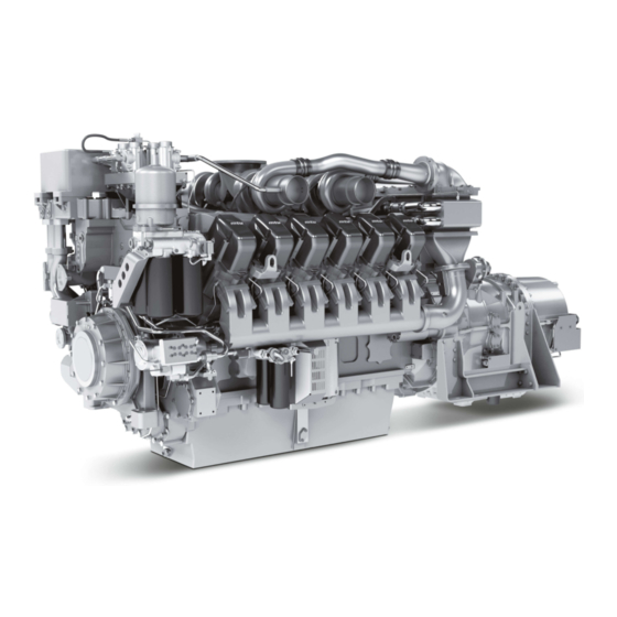
Page 19: Engine Layout
2.2 Engine layout Illustration is also valid for 16 V 4000 Sx3 engines 1 Oil heat exchanger 7 Flywheel 13 Cylinder head 2 Crankcase breather 8 Cylinder head cover 14 HP fuel pump 3 Air inlet connection 9 Engine lifting eye 15 Automatic oil filter (safety 4 Exhaust turbocharger 10 Oil pan... -
Page 20: Sensors And Actuators - Overview
2.3 Sensors and actuators – Overview Illustration also applies to 16 V 4000 Sx3 engines a Version with easy-change 3 B05 (lube oil pressure) 7 B34 (fuel pressure after fil- filter 4 B44 (turbocharger speed) ter) b Version with automatic fil- 5 Injectors Y39.1 to Y39.6 8 F46 (leak fuel level moni- (A bank) - Page 21 1 B50 (crankcase pressure) 4 B48 (fuel pressure in com- 7 B26 (charge-air coolant 2 B05 (lube oil pressure) mon rail) temperature) 3 B33 (fuel temperature in 5 B01 (camshaft speed) 8 B06 (coolant temperature) common rail) 6 B43 (charge-air coolant pressure) MS150026/02E 2013-11 | General Information | 21...
- Page 22 1 Injectors Y39.11 to 3 B10 (charge-air pressure) 5 B09 (charge-air tempera- Y39.16 (B bank) 4 XM2 (oil priming pump) ture) 2 B16 (coolant pressure) The injectors are located below the cylinder head covers. Injector replacement and necessary activities (→ Page 77). 22 | General Information | MS150026/02E 2013-11...
- Page 23 1 B13 (crankshaft speed) MS150026/02E 2013-11 | General Information | 23...
-
Page 24: Technical Data
3 Technical Data 3.1 12/16V 4000 S83 4D engine data EXPLANATION Abbr. Meaning Ref. value: Continuous power Ref. value: Fuel stop power Design value Guaranteed value Guideline value Limit value, up to which the engine can be operated, without change (e.g. of power setting) Not yet defined value Not applicable Applicable... - Page 25 CONSUMPTION Number of cylinders Lube oil consumption after 100 h % of B runtime (B = hourly fuel consump- tion) MODEL RELATED DATA (basic design) Number of cylinders Number of cylinders Cylinder arrangement: V-angle degrees Bore Stroke Displacement, cylinder Liters 4.77 4.77 Displacement, total...
- Page 26 COOLANT SYSTEM (LT circuit) Number of cylinders Coolant temperature (at engine °C connection: outlet to cooling equipment) Coolant temperature difference °C across intercooler, min. Coolant temperature difference °C across intercooler, max. Coolant antifreeze content, max. Charge-air temperature after in- °C tercooler, max.
- Page 27 INCLINATIONS, STANDARD OIL SYSTEM (reference: waterline) Number of cylinders Longitudinal inclination, continu- degrees ous max. driving end down (op- tion: max. operating inclinations) Longitudinal inclination, continu- degrees ous max., driving end up (option: max. operating inclinations) Transverse inclination continuous degrees max.
-
Page 28: Firing Order
3.2 Firing order Firing order Number of cylinders Firing order A1-B4-A4-A2-B3-A3-B2-B1 A1-B5-A5-B3-A3-B6-A6-B2-A2-B4-A4-B1 16 V A1-A7-B4-B6-A4-B8-A2-A8-B3-B5-A3-A5-B2-A6-B1-B7 20 V A1-B5-A8-B7-A5-B2-A7-B10-A2-B3-A10-B6-A3-B4-A6-B9-A4-B1-A9-B8 28 | Technical Data | MS150026/02E 2013-11... -
Page 29: Engine - Main Dimensions
3.3 Engine ‒ Main dimensions Engine ‒ Main dimensions Engine model Length (A) Width (B) Height (C) 12 V 4000 S83 approx. 2490 mm approx. 1449 mm approx. 1871 mm 16 V 4000 S83 approx. 2960 mm approx. 1449 mm approx. -
Page 30: Operation
4 Operation 4.1 Preparations for recommissioning the engine after extended out-of-service periods (>3 months) Preconditions ☑Engine shut down and secured against being restarted. ☑MTU Corrosion-proofing and Reproofing Regulations (A001070/..) are available. Recommissioning after long out-of-service periods (>3 months) Item Action Engine Remove corrosion-proofing (→... -
Page 31: Putting The Engine Into Operation After Scheduled Out-Of-Service-Period
4.2 Putting the engine into operation after scheduled out-of- service-period Preconditions ☑Engine is stopped and starting disabled. Startup Item Action Lube oil system Check engine oil level (→ Page 88). Coolant circuit Check engine coolant level (→ Page 101); Check charge-air coolant level (→ Page 114). Coolant circuit Preheat coolant with coolant preheating unit (if applicable). -
Page 32: Engine - Starting In Manual Mode
4.3 Engine – Starting in manual mode Preconditions ☑Engine is not under load. ☑External start interlock is not activated. DANGER Rotating and moving engine parts. Risk of crushing, danger of parts of the body being caught or pulled in! • Before cranking the engine with starter system, make sure that there are no persons in the en- gine's danger zone. -
Page 33: Operational Checks
4.4 Operational checks DANGER Rotating and moving engine parts. Risk of crushing, danger of parts of the body being caught or pulled in! • Only run the engine at low power. Keep away from the engine's danger zone. WARNING High level of engine noise when the engine is running. Risk of damage to hearing! •... -
Page 34: Engine - Stopping In Manual Mode
4.5 Engine – Stopping in manual mode Preconditions ☑Engine is not under load. ☑Engine is running in manual mode. NOTICE Stopping the engine when it is running at full load subjects it to extreme thermal and mechanical stresses. Overheating of and, therefore, damage to components is possible! •... -
Page 35: Preparing The Engine For Extended Out-Of-Service Period
Engine control system Switch off. Air intake and exhaust sys- Out-of-service-period > 1 week: • Seal engine's air and exhaust sides. Out-of-service-period > 1 month: • Preserve engine (→ MTU Preservation and Represervation Specifica- tions A001070/..). MS150026/02E 2013-11 | Operation | 35... -
Page 36: Plant - Cleaning
4.7 Plant – Cleaning Preconditions ☑Engine is stopped and starting disabled. ☑Operating voltage is not applied. Special tools, Material, Spare parts Designation / Use Part No. Qty. Steam jet cleaner Cleaner (Hakupur 312) 30390 WARNING Compressed air gun ejects a jet of pressurized air. Risk of injury to eyes and damage to hearing, risk of rupturing internal organs! •... -
Page 37: Maintenance
5 Maintenance 5.1 Maintenance task reference table [QL1] The maintenance tasks and intervals for this product are defined in the Maintenance Schedule. The Maintenance Schedule is a stand-alone publication. The task numbers in this table provide reference to the maintenance tasks specified in the Maintenance Schedule. -
Page 38: Troubleshooting
6 Troubleshooting 6.1 Troubleshooting Engine does not turn when starter is actuated Cause Corrective action u Charge or replace (see manufacturer's documentation). Battery low or faulty u Check if cable connections are properly secured (see Battery: Cable connections faulty manufacturer's documentation). Electric starter: Engine cabling u Check if cable connections are properly secured, contact or starter faulty... - Page 39 Contact Service. Engine governor defective Charge air temperature too high Cause Corrective action Engine coolant treatment u Check (MTU test kit). incorrect u Contact Service. Intercooler clogged u Check fans and intake/exhaust lines. Engine room: Air-intake temperature too high...
- Page 40 Blue exhaust gas Cause Corrective action Too much oil in engine u Drain engine oil (→ Page 89). Oil separator of crankcase u Replace (→ Page 68). breather contaminated u Contact Service. Exhaust turbocharger, cylinder head, piston rings, cylinder liner defective White exhaust gas Cause...
-
Page 41: Fault Messages From The Adec (Ecu 7) Engine Management Control Unit For The Series 4000 For C&I Applications
6.2 Fault messages from the ADEC (ECU 7) engine management control unit for the Series 4000 for C&I applications The fault code numbers are generated by the engine governor and transmitted to the following display unit. The fault code (1) is made up of two letters and three numbers. The letters (e.g. "SE") indicate some- thing about the device or the functional area that the message originates from. - Page 42 No. of as- sociated Fault code no. Description Meaning Action parameter Preliminary warning: fuel 2.0122.93 HI T-Fuel temperature too high. Contact Service. Main warning: fuel tempera- ture too high; engine shut- 2.0122.93 SS T-Fuel down. Contact Service. 1. Reduce power. Preliminary warning: charge- 2.
- Page 43 No. of as- sociated Fault code no. Description Meaning Action parameter 1. Check fuel sys- Leak fuel level too high (1st tem. 2.0151.93 HI Leak Fuel Level limit). 2. Contact Service. Turbocharger 2 idling speed 1.8004.20 HI ETC2 Idle Speed too high Contact Service.
- Page 44 No. of as- sociated Fault code no. Description Meaning Action parameter Engine must not be Main warning: crankcase restarted (risk of pressure too high; engine engine damage); 2.0106.93 SS P-Crankcase shutdown. contact Service. Check fuel lines for leaks. Clean fuel prefilter. Flush fuel prefilter.
- Page 45 No. of as- sociated Fault code no. Description Meaning Action parameter Engine speed remained be- low 200 rpm. Engine shut- Check for addition- 2.2500.03 AL Engine Stall down activated. al messages. SS Idle Speed Not Alarm configuration limit; 2.1090.92 Reached idling speed not attained.
- Page 46 No. of as- sociated Fault code no. Description Meaning Action parameter Internal power sup- ply (-15 V DC) fault; automat- Replace engine 15V POS ECU DEFECT ic engine shutdown. governor. Internal power sup- ply (-15 V DC) fault; automat- 15V NEG ECU DEFECT ic engine shutdown.
- Page 47 No. of as- sociated Fault code no. Description Meaning Action parameter Alarm configuration; connec- tion to a node on CAN bus 2 2.0500.68 AL CAN2 Node Lost failed. Contact Service. Alarm configuration; Incor- AL CAN Wrong Parame- rect parameter values en- 2.0500.68 ters tered in data record.
- Page 48 No. of as- sociated Fault code no. Description Meaning Action parameter AL EMU Parameter Not Alarm configuration; EMU pa- 2.0500.69 Supported rameters not supported. Contact Service. 1. Check wiring. Sensor B06 defective (cool- 2. Replace if neces- 1.8004.57 SD T-Coolant ant temperature).
- Page 49 No. of as- sociated Fault code no. Description Meaning Action parameter 2. Check error mes- sage; 3. Check wiring 4. Contact Service. 5. Check sensor. 1. Check sensor and wiring. 2. Replace if neces- sary. Sensor F25 defective (differ- Fault is cleared ential pressure sensor for en- when engine re- 1.8004.58...
- Page 50 No. of as- sociated Fault code no. Description Meaning Action parameter Check sensor and SD alarm configuration; wiring, replace as Backup engine oil pressure necessary. Fault is SD Oil Pressure redun- sensor defective; short cir- cleared when en- 1.8004.62 dant cuit or wire break gine restarted.
- Page 51 No. of as- sociated Fault code no. Description Meaning Action parameter 1.8004.51 1.8004.51 1.8004.51 1.8004.51 1.8004.51 1.8004.51 1.8004.51 1.8004.51 Wiring, bank 1 (solenoid 1. Check solenoid WIRING CYLINDER (A1- valve 1) ... wiring, bank 1 valve. 1.8004.52 A10) (solenoid valve 10) 2.
- Page 52 No. of as- sociated Fault code no. Description Meaning Action parameter 1.8004.53 1.8004.53 1.8004.53 1.8004.53 1.8004.53 1.8004.53 Open load, bank 1 (solenoid 1. Check solenoid OPEN_LOAD CYL.(A1- valve 1) ... open load, valve. 1.8004.54 A10) bank 1 (solenoid valve 10) 2.
- Page 53 No. of as- sociated Fault code no. Description Meaning Action parameter 1.8004.55 1.8004.55 1.8004.55 1.8004.55 Alarm configuration; internal electronic fault (electronics possibly defective: start ITS). 1. Check solenoid If ITS returns "Electronics valve wiring. OK", check other fault mes- 2. Replace engine 1.8004.49 AL Power Stage Low sages (e.g.
- Page 54 No. of as- sociated Fault code no. Description Meaning Action parameter Alarm configuration; Short circuit or wire break on tran- 1.8004.63 AL Wiring TO 4 sistor output 4 (TO 4). Alarm configuration; Short circuit or wire break on tran- sistor output 1, plant side Check cabling to 2.8006.63 AL Wiring TOP 1...
- Page 55 No. of as- sociated Fault code no. Description Meaning Action parameter Alarm configuration; wire 1. Check wiring. break at digital input 2; wir- 2. Contact Service.; AL Open Load Digital In- ing defective or no resist- Check input of tar- 2.8006.62 put 2 ance across switch.
- Page 56 No. of as- sociated Fault code no. Description Meaning Action parameter Alarm configuration limit 1; HI Water Level Fuel Pre- warning: water level in fuel 2.0156.93 filter prefilter too high. Drain water. Alarm configuration limit 1; preliminary warning: coolant pressure in intercooler too Top up coolant 2.0107.92 LO P-Coolant Intercooler...
- Page 57 No. of as- sociated Fault code no. Description Meaning Action parameter Alarm configuration limit 2; main warning: charge-air 2.0103.93 SS P-Charge Air pressure too high. Contact Service. Check signal trans- mitter and wiring, replace as necessa- SD alarm configuration; input signal for initial/final torque Fault is cleared SD Idle/End-Torque In-...
- Page 58 No. of as- sociated Fault code no. Description Meaning Action parameter Check temperature sensor and wiring, SD alarm configuration; ana- replace as necessa- log input for Aux 2 tempera- ry. Fault is cleared ture defective; short circuit when engine re- 1.8004.58 SD T-AUX 2 or wire break...
- Page 59 No. of as- sociated Fault code no. Description Meaning Action parameter AL Comb. Alarm Red Alarm configuration; RED Check other fault 2.8006.00 (Plant) combined alarm from plant. messages. Alarm configuration limit; in- Determine cause of Lim Ext. PlantEngine put signal above/below limit, limit violation and 2.0291.92 Prot bin...
-
Page 60: Task Description
7 Task Description 7.1 Engine 7.1.1 Engine – Performing test run DANGER Rotating and moving engine parts. Risk of crushing, danger of parts of the body being caught or pulled in! • Before cranking the engine with starter system, make sure that there are no persons in the en- gine's danger zone. -
Page 61: Engine - Barring Manually
7.1.2 Engine – Barring manually Preconditions ☑Engine is stopped and starting disabled. Special tools, Material, Spare parts Designation / Use Part No. Qty. Barring gear F6555766 Barring gear F6783293 Adapter F6558528 Ratchet with extension F30006212 DANGER Rotating and moving engine parts. Risk of crushing, danger of parts of the body being caught or pulled in! •... - Page 62 Barring engine manually (tool mounted underneath) Remove grounding device or guard plate. Engage barring gear (2) in ring gear (1) and mount on flywheel housing. • For 12/16V engines, use barring gear F6555766 with adapter F6558528. • For 20V engines, use barring gear F6783293.
-
Page 63: Engine - Barring With Starting System
7.1.3 Engine – Barring with starting system DANGER Rotating and moving engine parts. Risk of crushing, danger of parts of the body being caught or pulled in! • Before cranking the engine, make sure that there are no persons in the engine's danger zone. •... -
Page 64: Cylinder Liner
7.2 Cylinder Liner 7.2.1 Cylinder liner – Endoscopic examination Preconditions ☑Engine is stopped and starting disabled Special tools, Material, Spare parts Designation / Use Part No. Qty. Barring device F6555766 Ratchet with extension F30006212 Endoscope Y20097353 Preparatory steps Remove cylinder head cover (→ Page 75). Remove injector (→... - Page 65 Compile endoscopic report using the table. Use technical terms to describe the liner surface (→ Page 66). Depending on findings: • Do not take any action or • carry out a further endoscopic examination as part of maintenance work or •...
-
Page 66: Instructions And Comments On Endoscopic And Visual Examination Of Cylinder Liners
7.2.2 Instructions and comments on endoscopic and visual examination of cylinder liners Terms used for endoscopic examination Use the terms listed below to describe the condition of the cylinder-liner surface in the endoscopic ex- amination report. Findings Measure Light scoring Minor dirt scores can occur during the assembly of a new engine (honing prod- ucts, particles, broken-off burrs). - Page 67 Findings Measure Liners with heat discoloration starting in the TDC-ring 1 have to be replaced. Seizures, Seizure marks Seizure marks are of irregular circumferential length and depth. Can be caused by either the piston skirt or the piston crown. Material deposits on the liner (smears) show heavy discoloration and scoring.
-
Page 68: Crankcase Breather
7.3 Crankcase Breather 7.3.1 Crankcase breather – Oil separator replacement, diaphragm check and replacement Preconditions ☑Engine is stopped and starting disabled. Special tools, Material, Spare parts Designation / Use Part No. Qty. Torque wrench, 6-50 Nm F30027336 Ratchet F30027340 Engine oil Filter element (→... - Page 69 Checking diaphragm Remove cover (4). Remove spring (5), seal (2) and diaphragm (3). Check diaphragm (3) for damage, fit new diaphragm if used one is damaged. Install diaphragm (3) on housing (1). Install new seal (2) and spring (5) together with cover (4).
-
Page 70: Valve Drive
7.4 Valve Drive 7.4.1 Valve gear – Lubrication Preconditions ☑Engine is stopped and starting disabled. Special tools, Material, Spare parts Designation / Use Part No. Qty. Engine oil Valve gear – Lubrication Remove cylinder head covers (→ Page 75). Fill oil chambers of valve bridges with oil. Fill oil chambers of rocker arms and adjust- ing screws with oil. -
Page 71: Valve Clearance - Check And Adjustment
7.4.2 Valve clearance – Check and adjustment Preconditions ☑Engine is stopped and starting disabled. ☑Engine coolant temperature is max. 40 °C. ☑Valves are closed. Special tools, Material, Spare parts Designation / Use Part No. Qty. Feeler gauge Y20098771 Torque wrench, 60-320 Nm F30452768 Socket wrench, 24 mm F30039526... - Page 72 Diagram for 8V engines – Two crankshaft positions Diagram for 12V engines – Two crankshaft positions Diagram for 16V engines – Two crankshaft positions 72 | Task Description | MS150026/02E 2013-11...
- Page 73 Diagram for 20V engines – Two crankshaft positions Checking valve clearance at two crankshaft positions Check TDC position of piston in cylinder A1: • If the rocker arms are unloaded on cylinder A1, the piston is in firing TDC. • If the rocker arms are under load on cylinder A1, the piston is in overlap TDC. Check valve clearance with cold engine: •...
- Page 74 Tighten locknut (1) with torque wrench to the specified tightening torque, holding the adjusting screw (2) to prevent it from turning. Name Size Type Lubricant Value/Standard Locknut M16 x 1.5 Tightening torque (Engine oil) 90 Nm +9 Nm Replace or rectify adjusting screws and/or locknuts which do not move freely. Check valve clearance.
-
Page 75: Cylinder Head Cover - Removal And Installation
7.4.3 Cylinder head cover – Removal and installation Preconditions ☑Engine is stopped and starting disabled. Special tools, Material, Spare parts Designation / Use Part No. Qty. Grease (Kluthe Hakuform 30-11C/Emulgier) X00059351 O-ring (→ Spare Parts Catalog) Removing cylinder head cover Clean very dirty cylinder head covers (1) prior to removal. -
Page 76: Injection Pump / Hp Pump
7.5 Injection Pump / HP Pump 7.5.1 HP pump – Filling with engine oil Preconditions ☑Engine is stopped and starting disabled. Special tools, Material, Spare parts Designation / Use Part No. Qty. Engine oil WARNING Fuels are combustible. Risk of fire and explosion! •... -
Page 77: Injector
7.6 Injector 7.6.1 Injector – Replacement Special tools, Material, Spare parts Designation / Use Part No. Qty. Injector (→ Spare Parts Catalog) Injector – Replacement Remove injector and install new one (→ Page 78). MS150026/02E 2013-11 | Task Description | 77... -
Page 78: Injector - Removal And Installation
7.6.2 Injector – Removal and installation Preconditions ☑Engine is stopped and starting disabled. Special tools, Material, Spare parts Designation / Use Part No. Qty. Installation/removal tool F6789889 Milling cutter F30452739 Torque wrench, 0.5-5 Nm 0015384230 Torque wrench, 10-60 Nm F30452769 Ratchet F30027340 Torque wrench, 60-320 Nm... - Page 79 Remove HP fuel line (4). Note: While the adapter is removed, the injector is drained. Remove adapter (3). Remove screw (2) and take off hold-down clamp (1). Install installation/removal tool on cylinder head. Remove injector with installation/removal tool. Remove installation/removal tool. Remove sealing ring (4) from injector or use a self-made hook to take it out of the cylinder head.
- Page 80 Installing injector Remove plug before installing the injec- tor. (Do not remove the plug from the HP line before installing the adapter.) Coat injector with assembly paste at the seat of the nozzle retaining nut. Fit new sealing ring (included in the scope of supply of the injector) with grease on in- jector, observe installation position of seal- ing ring.
- Page 81 Coat bolt mating face (2) and thread with engine oil. Fit hold-down clamp (1) in the correct position and use torque wrench to tighten screw (2) to the speci- fied initial tightening torque. Name Size Type Lubricant Value/Standard Screw Preload torque (Engine oil) 5 Nm to 10 Nm Note:...
- Page 82 Fit connectors on injector. Note: Failure to reset drift compensation (CDC) will void the emissions certification. Reset drift compensation (CDC) with Dia- Sys® (→ E531920/...). If DiaSys® is not available, contact Service. Final steps Install cylinder head cover (→ Page 75). Open fuel supply to engine.
-
Page 83: Fuel System
7.7 Fuel System 7.7.1 Fuel system – Venting Preconditions ☑Engine is stopped and starting disabled. Special tools, Material, Spare parts Designation / Use Part No. Qty. Diesel fuel WARNING Fuels are combustible. Risk of fire and explosion! • Avoid open flames, electrical sparks and ignition sources. •... -
Page 84: Fuel Filter
7.8 Fuel Filter 7.8.1 Fuel filter – Replacement Preconditions ☑Engine is stopped and starting disabled. Special tools, Material, Spare parts Designation / Use Part No. Qty. Filter wrench F30379104 Engine oil Easy-change filter (→ Spare Parts Catalog) WARNING Fuels are combustible. Risk of fire and explosion! •... -
Page 85: Charge-Air Cooling
7.9 Charge-Air Cooling 7.9.1 Intercooler – Checking condensate drain for coolant leakage and obstruction DANGER Rotating and moving engine parts. Risk of crushing, danger of parts of the body being caught or pulled in! • Only run the engine at low power. Keep away from the engine's danger zone. WARNING High level of engine noise when the engine is running. -
Page 86: Starting Equipment
7.10 Starting Equipment 7.10.1 Starter – Condition check Preconditions ☑Engine is stopped and starting disabled. Checking starter condition Check securing screws of starter for secure seating and tighten if required. Check wiring (→ Page 124). 86 | Task Description | MS150026/02E 2013-11... -
Page 87: Air Intake
7.11 Air Intake 7.11.1 Emergency air-shutoff flaps – Electric control check DANGER Rotating and moving engine parts. Risk of crushing, danger of parts of the body being caught or pulled in! • Before cranking the engine with starter system, make sure that there are no persons in the en- gine's danger zone. -
Page 88: Lube Oil System, Lube Oil Circuit
7.12 Lube Oil System, Lube Oil Circuit 7.12.1 Engine oil ‒ Level check Checking oil level before start- ing engine Remove oil dipstick from guide tube and wipe it clean. Insert dipstick into guide tube up to the stop. Pull out after approx. 10 seconds and check oil level. -
Page 89: Engine Oil - Change
7.12.2 Engine oil – Change Preconditions ☑Engine is stopped and starting disabled. ☑Engine is at operating temperature. ☑MTU Fluids and Lubricants Specifications (A001061/..) are available. Special tools, Material, Spare parts Designation / Use Part No. Qty. Torque wrench, 40-200 Nm... - Page 90 Draining residual oil from equip- ment carrier (only with unsched- uled engine oil change) Provide a suitable container in which to col- lect the engine oil. Remove drain plug (1) and drain oil (ap- prox. 7 liters) from oil heat exchanger and oil filter.
-
Page 91: Engine Oil - Sample Extraction And Analysis
7.12.3 Engine oil – Sample extraction and analysis Preconditions ☑MTU Fluids and Lubricants Specifications (A001061/..) are available. Special tools, Material, Spare parts Designation / Use Part No. Qty. MTU test kit 5605892099/00 DANGER Rotating and moving engine parts. Risk of crushing, danger of parts of the body being caught or pulled in! •... -
Page 92: Oil Filtration / Cooling
7.13 Oil Filtration / Cooling 7.13.1 Engine oil filter – Replacement Preconditions ☑Engine is stopped and starting disabled. Special tools, Material, Spare parts Designation / Use Part No. Qty. Filter wrench F30379104 Engine oil Oil filter (→ Spare Parts Catalog) WARNING Hot oil. -
Page 93: Automatic Oil Filter - Filter Candles Replacement
7.13.2 Automatic oil filter – Filter candles replacement Preconditions ☑Engine is stopped and starting disabled. Special tools, Material, Spare parts Designation / Use Part No. Qty. Torque wrench, 10-60 Nm F30452769 Ratchet adapter F30027340 Torque wrench, 60-320 Nm F30452768 Ratchet F30027342 Grease (Kluthe Hakuform 30-11C/Emulgier) X00059351... - Page 94 Withdraw filter insert (1). Remove O-ring. Replacing oil filter candles Remove screw (2). Withdraw spinner (1) with spring. Remove nut (3). Take off spring washer and washer. Remove screw (4). Remove flushing arm (5) from screen plate (6). Turn filter insert upside down and use ap- propriate tool to push out filter candles (1).
- Page 95 Replace all sealing elements. Insert O-rings in grooves. Install strainer plate (6) and flushing arm (5). Note: Observe the position of the screw to the elongated hole in the shaft. Screw in screw (4). Install washer and spring washer. Tighten nut (3) to specified tightening torque using a torque wrench. Name Size Type...
- Page 96 Install oil filter cover (1). Install nuts (2) of oil filter cover (1). 96 | Task Description | MS150026/02E 2013-11...
-
Page 97: Oil Indicator Filter - Cleaning And Check
7.13.3 Oil indicator filter – Cleaning and check Preconditions ☑Engine is stopped and starting disabled. Special tools, Material, Spare parts Designation / Use Part No. Qty. Cleaning agent (Snow-White 11-0) 40460 Cleaning agent (Hakupur 312) 30390 Engine oil Strainer (→ Spare Parts Catalog) Square-section ring (→... - Page 98 Checking strainer Item Findings Action • Clean Strainer Metallic residues • Monitor engine operation • Check strainer daily • Contact Service Strainer Damaged Fit new part Square-section ring Damaged Fit new part O-ring Damaged Fit new part Cleaning strainer Wash strainer (5) with cleaner. Remove stubborn deposits with soft brush.
-
Page 99: Centrifugal Oil Filter - Cleaning And Filter-Sleeve Replacement
7.13.4 Centrifugal oil filter – Cleaning and filter-sleeve replacement Preconditions ☑Engine is stopped and starting disabled. Special tools, Material, Spare parts Designation / Use Part No. Qty. Torque wrench, 6-50 Nm F30027336 Cold cleaner (Hakutex 60) X00056750 Filter sleeve (→ Spare Parts Catalog) Sealing ring (→... - Page 100 Centrifugal oil filter – Cleaning and filter-sleeve replacement Remove clamp (14). Release Tommy nut (2) and take off cov- er (1). Carefully lift rotor (11), allow oil to drain and remove from housing. Holding the rotor (11) firmly, release rotor cover nut (3).
-
Page 101: Engine Coolant – Level Check
7.14 Coolant Circuit, General, High-Temperature Circuit 7.14.1 Engine coolant – Level check Preconditions ☑Engine is stopped and starting disabled. ☑MTU Fluids and Lubricants Specifications (A001061/..) are available. WARNING Coolant is hot and under pressure. Risk of injury and scalding! • Let the engine cool down. - Page 102 7.14.2 Engine coolant – Change Special tools, Material, Spare parts Designation / Use Part No. Qty. Coolant Engine coolant change Drain engine coolant (→ Page 104). Fill with engine coolant (→ Page 106). 102 | Task Description | MS150026/02E 2013-11...
-
Page 103: Engine Coolant Pump Pressure Relief Port
7.14.3 Engine coolant pump pressure relief port – Check DANGER Rotating and moving engine parts. Risk of crushing, danger of parts of the body being caught or pulled in! • Only run the engine at low power. Keep away from the engine's danger zone. WARNING High level of engine noise when the engine is running. - Page 104 7.14.4 Draining engine coolant Preconditions ☑Engine shut down and secured against being restarted. WARNING Coolant is hot and under pressure. Risk of injury and scalding! • Let the engine cool down. • Wear protective clothing, gloves, and goggles / safety mask. Preparatory steps Have a suitable container ready to catch the coolant.
- Page 105 Open the drainage point on the main PTO end of the crankcase, on the left or right side (arrowed) and drain off the engine coolant. Close off all open drain points. Place pressure cap on filler neck and close. Concluding operations Switch on preheater.
- Page 106 7.14.5 Engine coolant – Filling Preconditions ☑Engine is stopped and starting disabled. ☑MTU Fluids and Lubricants Specifications (A001061/..) are available. Special tools, Material, Spare parts Designation / Use Part No. Qty. Engine coolant WARNING Coolant is hot and under pressure.
- Page 107 Filling with coolant using pump Connect a suitable pump with a hose to drain valve. Open drain valve and pump coolant into en- gine at 0.5 bar minimum. Fill expansion tank until overflow edge is reached. Close drain valve. Check proper condition of breather valve and clean sealing faces if required.
-
Page 108: Analysis
7.14.6 Engine coolant – Sample extraction and analysis Preconditions ☑MTU Fluids and Lubricants Specifications (A001061/..) are available. Special tools, Material, Spare parts Designation / Use Part No. Qty. MTU test kit 5605892099/00 DANGER Rotating and moving engine parts. Risk of crushing, danger of parts of the body being caught or pulled in! •... - Page 109 7.14.7 Engine coolant filter – Replacement Preconditions ☑Engine is stopped and starting disabled. Special tools, Material, Spare parts Designation / Use Part No. Qty. Filter wrench F30379104 Engine oil Coolant filter (→ Spare Parts Catalog) WARNING Coolant is hot and under pressure. Risk of injury and scalding! •...
- Page 110 7.15 Low-Temperature Circuit 7.15.1 Charge-air coolant – Change Special tools, Material, Spare parts Designation / Use Part No. Qty. Coolant Charge-air coolant – Change Drain charge-air coolant (→ Page 111). Fill with charge-air coolant (→ Page 112). 110 | Task Description | MS150026/02E 2013-11...
- Page 111 7.15.2 Charge-air coolant – Draining Preconditions ☑Engine shut down and secured against being restarted. Special tools, Material, Spare parts Designation / Use Part No. Qty. Sealing ring (→ Spare Parts Catalog) WARNING Coolant is hot and under pressure. Risk of injury and scalding! •...
-
Page 112: Charge-Air Coolant – Filling
7.15.3 Charge-air coolant – Filling Preconditions ☑Engine is stopped and starting disabled. ☑MTU Fluids and Lubricants Specifications (A001061/..) are available. Special tools, Material, Spare parts Designation / Use Part No. Qty. Charge-air coolant WARNING Coolant is hot and under pressure. - Page 113 Filling with charge-air coolant using pump Connect appropriate pump with hose to drain valve (arrow). Open drain valve and pump coolant into en- gine at 0.5 bar minimum. Fill expansion tank until overflow edge is reached. Close drain valve. Check proper condition of breather valve and clean sealing faces if required.
-
Page 114: Charge-Air Coolant – Level Check
7.15.4 Charge-air coolant – Level check Preconditions ☑Engine is stopped and starting disabled. ☑MTU Fluids and Lubricants Specifications (A001061/..) are available. WARNING Coolant is hot and under pressure. Risk of injury and scalding! • Let the engine cool down. • Wear protective clothing, gloves, and goggles / safety mask. - Page 115 7.15.5 Charge-air coolant pump – Relief bore check DANGER Rotating and moving engine parts. Risk of crushing, danger of parts of the body being caught or pulled in! • Only run the engine at low power. Keep away from the engine's danger zone. WARNING High level of engine noise when the engine is running.
- Page 116 7.16 Belt Drive 7.16.1 Drive belt – Condition check Preconditions ☑Engine is stopped and starting disabled. ☑Guard is removed. Drive belt – Condition check Item Findings Action Drive belt A Singular cracks None Drive belt B Cracks on entire circumference Replace (→...
-
Page 117: Battery-Charging Generator
7.17 Battery-Charging Generator 7.17.1 Battery-charging generator ‒ Check Preconditions ☑Engine is stopped and starting disabled. WARNING Compressed air gun ejects a jet of pressurized air. Risk of injury to eyes and damage to hearing, risk of rupturing internal organs! • Never direct air jet at people. •... - Page 118 7.17.2 Battery-charging generator drive – Drive belt tension adjustment Preconditions ☑Engine is stopped and starting disabled. Special tools, Material, Spare parts Designation / Use Part No. Qty. Torque wrench, 60-320 Nm F30452768 Ratchet F30027341 Torque wrench, 10-60 Nm F30452769 Ratchet F30027340 WARNING Spring/circlip/tensioning roller preload.
-
Page 119: Replacement
7.17.3 Battery-charging generator drive – Drive belt replacement Preconditions ☑Engine is stopped and starting disabled. Special tools, Material, Spare parts Designation / Use Part No. Qty. Torque wrench, 60-320 Nm F30452768 Ratchet F30027341 Torque wrench, 10-60 Nm F30452769 Ratchet F30027340 Drive belt (→... - Page 120 Hold measuring tip of belt tension tester over belt drive. Tap drive belt (arrow) with a suitable tool. Hold belt tension tester over belt drive until the measured value is indicated. Initial assembly at MTU Initial operation with fan Re-tensioning None 60 Hz ±1 Hz 52 Hz ±1 Hz...
- Page 121 Hold measuring tip of belt tension tester over belt drive. Tap drive belt (arrow) with a suitable tool. Hold belt tension tester over belt drive until the measured value is indicated. Initial assembly at MTU Initial operation with fan Re-tensioning 36 Hz ±5 Hz 49 Hz ±2 Hz...
- Page 122 7.18.2 Fan drive – Drive belt replacement Preconditions ☑Engine is stopped and starting disabled. Special tools, Material, Spare parts Designation / Use Part No. Qty. Drive belt (→ Spare Parts Catalog) Preparatory steps Remove protective cover. Remove fan. Replacing drive belt Release screws (2).
- Page 123 7.19 Engine Mounting / Support 7.19.1 Engine mounting – Check Engine mounting – Check Item Findings Action • Damage Visually inspect mounts. Replace (contact Service). • Brittleness • Deformation • Crack formation • Swelling visible MS150026/02E 2013-11 | Task Description | 123...
- Page 124 7.20 Wiring (General) for Engine/Gearbox/Unit 7.20.1 Engine wiring – Check Preconditions ☑Engine is stopped and starting disabled. Special tools, Material, Spare parts Designation / Use Part No. Qty. Isopropyl alcohol X00058037 Checking engine wiring Check securing screws of cable clamps on engine and tighten loose threaded connections. Ensure that cables are fixed in their clamps and cannot swing freely.
- Page 125 7.21 Accessories for (Electronic) Engine Governor / Control System 7.21.1 CDC parameters – Reset with DiaSys® Preconditions ☑Engine is stopped and starting disabled. Resetting CDC parameters (DiaSys® is available) Note: The CDC parameters must be reset, otherwise the emission certification of the engine is no longer ap- plicable.
- Page 126 7.21.2 Engine governor and connectors – Cleaning Preconditions ☑Engine is stopped and starting disabled. Special tools, Material, Spare parts Designation / Use Part No. Qty. Isopropyl alcohol X00058037 Note: Always use test connectors to enter the connectors. Never use test leads for this purpose. Otherwise the contacts could be bent.
- Page 127 7.21.3 Engine governor plug connections – Check Preconditions ☑Engine stopped and starting disabled. NOTICE Insertion of unsuitable test probe, e.g. test prod. The contacts in the plug connection can be bent! • Carry out check of plug connection only with test connectors. Checking plug connections at engine governor Check all plug connections for secure seating.
- Page 128 Association of American standardization organiza- tions Exhaust turbocharger/exhaust turbocharg- Air Temperature Sensor Baureihe (Series) Betriebsstoffvorschrift (Fluids and Lubri- MTU Publication No. A01061/.. cants Specifications) Controller Area Network Data bus system, bus standard Calibration Drift Compensation Drift correction setting with DiaSys in engine gover-...
- Page 129 Abbre- Meaning Explanation viation Engine Data Module Memory module for engine data Electrically Erasable Programmable Read PROM Only Memory EFPA Electronic Foot Pedal Assembly Electronic accelerator pedal Exhaust Gas Recirculation Engine Ident Label Engine Monitoring Unit Engine monitoring unit ESCM Extreme Site Condition Management Power reduction with extreme site conditions Spare Parts Catalog...
- Page 130 Abbre- Meaning Explanation viation Original Equipment Manufacturer Optimized Idle Oil Level Sensor Monitors oil level Oil pressure sensor Monitors oil pressure Oil Temperature Sensor Monitors oil temperature Top Dead Center Panel Control panel Peripheral Interface Module Pulse Width Modulation Modulated signal P-xyz Pressure-xyz Pressure measuring point xyz...
- Page 131 Local support Experienced and qualified specialists place their knowledge and expertise at your disposal. For locally available support, go to the MTU Internet site: http://www.mtu-online.com 24h hotline With our 24h hotline and the outstanding flexibility of our service staff, we are always ready to assist you –...
- Page 132 9 Appendix B 9.1 Special Tools Adapter Part No.: F6558528 Qty.: Used in: 7.1.2 Engine – Barring manually (→ Page 61) Barring device Part No.: F6555766 Qty.: Used in: 7.2.1 Cylinder liner – Endoscopic examination (→ Page 64) Barring gear Part No.: F6555766 Qty.:...
- Page 133 Barring gear Part No.: F6783293 Qty.: Used in: 7.1.2 Engine – Barring manually (→ Page 61) Endoscope Part No.: Y20097353 Qty.: Used in: 7.2.1 Cylinder liner – Endoscopic examination (→ Page 64) Feeler gauge Part No.: Y20098771 Qty.: Used in: 7.4.2 Valve clearance –...
- Page 134 7.6.2 Injector – Removal and installation (→ Page 78) Milling cutter Part No.: F30452739 Qty.: Used in: 7.6.2 Injector – Removal and installation (→ Page 78) MTU test kit Part No.: 5605892099/00 Qty.: Used in: 7.12.3 Engine oil – Sample extraction and analysis (→ Page 91) Qty.:...
- Page 135 Ratchet Part No.: F30027340 Qty.: Used in: 7.3.1 Crankcase breather – Oil separator replacement, diaphragm check and replacement (→ Page 68) Qty.: Used in: 7.6.2 Injector – Removal and installation (→ Page 78) Qty.: Used in: 7.17.2 Battery-charging generator drive – Drive belt tension adjustment (→...
- Page 136 Ratchet adapter Part No.: F30027340 Qty.: Used in: 7.13.2 Automatic oil filter – Filter candles replacement (→ Page 93) Ratchet with extension Part No.: F30006212 Qty.: Used in: 7.1.2 Engine – Barring manually (→ Page 61) Qty.: Used in: 7.2.1 Cylinder liner – Endoscopic examination (→...
- Page 137 Torque wrench, 0.5-5 Nm Part No.: 0015384230 Qty.: Used in: 7.6.2 Injector – Removal and installation (→ Page 78) Torque wrench, 10-60 Nm Part No.: F30452769 Qty.: Used in: 1.4 Crankshaft transport locking device (→ Page 8) Qty.: Used in: 7.6.2 Injector –...
- Page 138 Torque wrench, 60-320 Nm Part No.: F30452768 Qty.: Used in: 1.4 Crankshaft transport locking device (→ Page 8) Qty.: Used in: 7.4.2 Valve clearance – Check and adjustment (→ Page 71) Qty.: Used in: 7.6.2 Injector – Removal and installation (→ Page 78) Qty.: Used in: 7.13.2 Automatic oil filter –...
- Page 139 9.2 Index Numerics 12/16V 4000 S83 4D engine data 24 Designations – Engine sides and cylinders 18 Drive belt Abbreviations 128 – Condition check 116 Actuators – Overview 20 Automatic oil filter Emergency air-shutoff flaps – Filter candles replacement 93 – Electric control check 87 Engine ...
- Page 140 – Checking condensate drain for coolant leakage 85 Troubleshooting 38 – Checking condensate drain for obstructions 85 Valve clearance Main engine dimensions 29 – Adjustment 71 MTU contact persons 131 – Check 71 Valve gear – Lubrication 70 Oil indicator filter – Check 97 –...
Need help?
Do you have a question about the 12V4000S83 and is the answer not in the manual?
Questions and answers