Table of Contents
Advertisement
CAUTION, MICROWAVE RADIATION .............................................................................................................. 1
WARNING ............................................................................................................................................................1
PRODUCT SPECIFICATIONS ........................................................................................................................... 2
GENERAL INFORMATION ................................................................................................................................. 2
APPEARANCE VIEW ......................................................................................................................................... 3
OPERATION SEQUENCE ................................................................................................................................. 4
FUNCTION OF IMPORTANT COMPONENTS ................................................................................................... 5
SERVICING ........................................................................................................................................................ 6
TEST PROCEDURE .......................................................................................................................................... 8
COMPONENT REPLACEMENT AND ADJUSTMENT PROCEDURE ............................................................. 13
MICROWAVE MEASUREMENT ...................................................................................................................... 19
WIRING DIAGRAM .......................................................................................................................................... 20
PICTORIAL DIAGRAM ..................................................................................................................................... 21
PARTS LIST ...................................................................................................................................................... 22
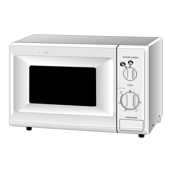
SERVICE MANUAL
COOKING CONTROL
TIMER
DEFROST (Kg)
0
30
MODEL
1 kg
5
10
25
15
20
0.5 kg
OPEN DOOR
In interests of user-safety the oven should be restored to its original
condition and only parts identical to those specified should be used.
TABLE OF CONTENTS
SHARP CORPORATION
MICROWAVE OVEN
R-211A
R-211A
S5709R211APX/
Page
Advertisement
Table of Contents
Troubleshooting

Subscribe to Our Youtube Channel
Related Manuals for Sharp R-211A


Summary of Contents for Sharp R-211A
-
Page 1: Table Of Contents
R-211A SERVICE MANUAL S5709R211APX/ MICROWAVE OVEN COOKING CONTROL TIMER DEFROST (Kg) R-211A MODEL 1 kg 0.5 kg OPEN DOOR In interests of user-safety the oven should be restored to its original condition and only parts identical to those specified should be used. - Page 2 R-211A...
-
Page 3: Caution Microwave Radiation
PRODUCT SPECIFICATIONS R-211A GENERAL IMPORTANT INFORMATION APPEARANCE VIEW This Manual has been prepared to provide Sharp Corp. Service engineers with Operation and Service Information. It is recommended that service engineers carefully study the OPERATING SEQUENCE entire text of this manual, so they will be qualified to render satisfactory customer service. -
Page 4: Product Description
R-211A PRODUCT DESCRIPTION SPECIFICATION ITEM DESCRIPTION Power Requirements 220 Volts 50 Hertz Single phase, 3 wire earthed Power Consumption 1.06 KW Power Output 700 watts nominal of RF microwave energy (IEC-705-1988) Operating fequency 2450 MHz Case Dimensions Width 450 mm... -
Page 5: Appearance View
R-211A APPEARANCE VIEW OVEN COOKING CONTROL TIMER DEFROST (Kg) 1 kg 0.5 kg OPEN DOOR 1. Power supply cord 6. Coupling 7. Control panel 2. Oven lamp 3. Door hinges 8. Door lock openings 4. Safety door latches 9. Ventilation openings 5. -
Page 6: Operation Sequence
R-211A OPERATION SEQUENCE OFF CONDITION cycle of a cooking program, the 1st latch switch and 2nd latch switch must open their (COM-NO) contacts 1. When the timer knob is at " 0 ", the oven is OFF first. After that the contacts (COM-NC) of the monitor condition. -
Page 7: Function Of Important Components
R-211A FUNCTION OF IMPORTANT COMPONENTS DOOR OPEN MECHANISM TEMPEATURE FUSE 120˚C (OVEN) The door is opened by pushing the open button on the The temp. fuse located on the top of the oven cavity is control panel, refer to the Figure D-1. -
Page 8: Servicing
Sharp recommend that wherever possible fault-finding is carried out with the supply disconnected. It may in, some cases, be necessary to connect the supply after the outer case has been removed, in this event carry out 3D checks and then disconnect the leads to the primary of the power transformer. -
Page 9: Troubleshooting Chart
R-211A TROUBLESHOOTING CHART TEST PROCEDURE A B C D E E E G G J J J H H I POSSIBLE CAUSE DEFECTIVE PARTS PROBLEM CONDITION M6.3A Fuse blows when power cord is plugged into wall outlet. M6.3A CONDITION Fuse blows when the door is opened. -
Page 10: Test Procedure
R-211A TEST PROCEDURES PROCEDURE COMPONENT TEST LETTER MAGNETRON TEST NEVER TOUCH ANY PART IN THE CIRCUIT WITH YOUR HAND OR AN INSULATED TOOL WHILE THE OVEN IS IN OPERATION. CARRY OUT 3D CHECKS. Isolate the magnetron from the high voltage circuit by removing all leads connected to the filament terminal. - Page 11 R-211A TEST PROCEDURES PROCEDURE COMPONENT TEST LETTER Initial temperature ....................T1 = 11°C Temperature after (60 + 2) = 62 sec..............T2 = 21°C Temperature difference Cold-Warm ..............∆T1 = 10°C Measured output power The equation is “P = 70 x ∆T” ............P = 70 x 10°C = 700 Watts ±...
- Page 12 R-211A TEST PROCEDURES PROCEDURE COMPONENT TEST LETTER HIGH VOLTAGE CAPACITOR TEST CARRY OUT 3D CHECKS. A. Isolate the high voltage capacitor from the circuit. B. Continuity check must be carried out with measuring instrument which is set to the highest resistance range.
- Page 13 R-211A TEST PROCEDURES PROCEDURE COMPONENT TEST LETTER If incorrect readings are obtained, replace the temperature fuse or thermal cut-out. An open circuit thermal cut-out (MG) indicates that the magnetron has overheated, this may be due to resistricted ventilation, cooling fan failure or a fault condition within the magnetron or HV circuit.
- Page 14 R-211A TEST PROCEDURES PROCEDURE COMPONENT TEST LETTER DEFROST SWITCH - CONTACTS Before proceeding with this part of the test, check the relay coil as outlined above. WARNING: This test requires the oven to be operated with supply connected. Follow the instruction below carefully.
-
Page 15: Component Replacement And Adjustment Procedure
R-211A COMPONENT REPLACEMENT AND ADJUSTMENT PROCEDURE WARNING: Avoid possible exposure to microwave energy. Please follow the instructions below before operating the oven. 1. Disconnect oven from power supply. 1. Door does not close firmly. 2. Make sure that a definite” click” can be heard when the 2. - Page 16 R-211A MAGNETRON REPLACEMENT Removal CAUTION: WHEN REPLACING THE MAGNETRON, 1. CARRY OUT 3D CHECKS. BE SURE THE R.F. GASKET IS IN PLACE 2. Disconnect the wire leads from the magnetron. AND THE MAGNETRON MOUNTING 3. Carefully remove the two (2) screws holding the mag- SCREWS ARE TIGHTENED SECURELY.
-
Page 17: Turntable Motor Replacement
Re-install oven cavity. 3. Turn the oven over. 1. Remove the any sharp edges on the turntable motor 4. Cut the four (4) bridges holding the turntable motor cover and the bottom plate with the cutting pliers. cover to the bottom plate with the cutting pliers as 2. - Page 18 R-211A FAN MOTOR REPLACEMENT REMOVAL 1. CARRY OUT 3D CHECKS. INSTALLATION 2. Disconnect the wire leads from the fan motor. Install the fan motor to the fan duct with the two (2) 3. Remove the one (1) screw holding the chassis support screws.
- Page 19 R-211A 2. Re-connect wire leads to each switch. Refer to chapter 5. Re-connect wire leads to the timer motor. Refer to "Pictorial Diagram". chapter "Pictorial Diagram". 3. Secure latch hook (with two (2) mounting screws) to 6. Make sure that monitor switch is operating properly oven flange.
- Page 20 R-211A and figure C-10, on how to handle the new film. 5. Catch two (2) pins of door panel on two (2) hole of upper Sealer film Backing film and lower oven hinges. 6. Re-install choke cover to door panel by pushing.
-
Page 21: Microwave Measurement
R-211A MICROWAVE MEASUREMENT Recommended instruments are: After adjustment of door latch switches, monitor switch NARDA 8100 and door are completed individually or collectively, the NARDA 8200 following leakage test must be performed with a survey HOLADAY HI 1500 instrument and it must be confirmed that the result meets... -
Page 22: Wiring Diagram
R-211A SCHEMATIC NOTE: CONDITION OF OVEN 1. TIMER OFF. NOTE: " " indicates components with potential above 250V. 2. DOOR CLOSED. 1ST. LATCH MONITOR SWITCH FUSE M6.3A MAIN DEFROST TEMPERATURE SWITCH SWITCH FUSE120˚C (OVEN) POWER SELECT SWITCH THERMAL 2ND. CUT-OUT LATCH 95˚C (MG) -
Page 23: Pictorial Diagram
R-211A... -
Page 24: Parts List
R-211A PARTS LIST ∆ Note: The parts marked " " may cause undue microwave exposure. The parts marked " " are used in voltage more than 250V. REF. NO. PART NO. DESCRIPTION Q'TY CODE ELECTRIC PARTS 1- 1 QSWTEA123WRE0 Timer motor... - Page 25 R-211A ∆ Note: The parts marked " " may cause undue microwave exposure. The parts marked "*" are used in voltage more than 250V. REF. NO. PART NO. DESCRIPTION Q'TY CODE 6- 8 PSHE-A074WRR0 Menu label 6- 9 TCADCA565WRR0 Cook book in Thai...
- Page 26 R-211A OVEN AND CABINET PARTS 1-13 1-11 6-13 7-10 1-17 1-18 4-17 1-15 1-12 1-10 4-13 4-14 6-11 6-12 4-11 4-12 4-16 1-14 4-10 4-15 1-16...
- Page 27 R-211A CONTROL PANEL PARTS DOOR PARTS MISCELLANEOUS 6-10 6-11 Actual wire harness may be different than illustration.
- Page 28 R-211A '97SHARP CORP. (6K0.070E) Printed in Japan...
Need help?
Do you have a question about the R-211A and is the answer not in the manual?
Questions and answers