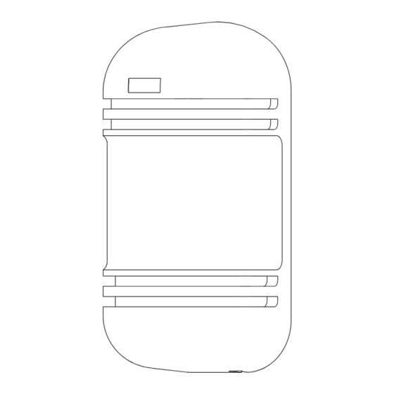
Table of Contents
Advertisement
Quick Links
DIGITAL ACTIVE INFRARED SENSOR
INSTRUCTION MANUAL
2
SUGGESTIONS FOR INSTALLATION 1
Ensure the sensors line of sight is
Ensure the sensors are
free from any false alarm sources
mounted on a stable and
such as bushes, trees, etc. ( Pay
firm fixing.
attention to these as they may
change seasonally.)
3
SUGGESTIONS FOR INSTALLATION 2
Note that here the protection distances
refers to the sheet below.
Protection
Spread of
Model
Distance
Beam
SBT-30S
30m
0.9m
SBT-40S
1.2m
40m
SBT-60S
60m
1.8m
80m
2.4m
SBT-80S
100m
3.0m
SBT-100S
4
INSTALLATION
1. Loosen screw holding cover and
remove the cover.
4. Attach the unit to the wall.
Wiring distance
Model
SBT-30S
SBT-40S
Voltage
Wire
12V
24V
12V
diameter
φ
2
0.3mm ( 0.6)
280m
2400m
270m
2
φ
0.5mm ( 0.8)
500m
4400m
477m
φ
2
0.75mm ( 1.0)
780m
7000m
747m
2
φ
1.25mm ( 1.2)
1120m
10000m
1074m
SBT - 30S
SBT - 40S
SBT - 60S
SBT - 80S
SBT-100S
Ensure strong sunlight or car
headlights do not shine directly
on to the receiver. (Within ±2°
from the optical axis is not
recommended.)
Height of installation and
protection distance
33mm
14mm
33mm
0.7
~
1.0m
Protection Distance
WALL MOUNT
2.
Attach the mounting pattern
3. Break knock-out and pull wire
paper to the wall, mark the
installation holes, and make
guide holes.
5. Connect wires to the terminal.
6.
SBT-60S
SBT-80/100S
24V
12V
24V
12V
24V
2300m
250m
2100m
190m
1600m
4200m
430m
3800m
350m
3000m
6700m
680m
6100m
546m
4900m
9570m
980m
8700m
784m
7000m
1
PARTS DESCRIPTION
① LED
GOOD
RECEIVER
●GOOD ( Green )
On when optically aligned
Off when optically not aligned
●LEVEL ( Red )
Intensity varies with signal
●ALARM
Alarm indication lamp
② Monitor jack: Should be used for making the optimum optical axis adjustment
③ Obscuration time adjustment: To be used for setting the obscuration time
Direction of installation
Horizontally 180°
Because angle of reflection mirror is adjustable
in
±
90°horizontally and
unit can be installed in various directions.
through.
knock-out
Make the optimum optical adjustment
as per section 5 and confirm system
operation before replacing covers.
TERMINAL CONFIGURATION
POWER ALARM
TAMPER
1
2
3
4
5
6
7
RECEIVER
POWER
FREE TAMPER
1
2
3
4
5
6
7
TRANSMITTER
Wire Hole
Connection
Terminal
① LED
Vertical
Adjustment
Screw
LENS
Cover Lock
Screw
COVER
MAIN BODY
LEVEL ALARM
TRANSMITTER
●POWER ( Green )
( Refer to ' how to use the monitor jack' )
( Refer to ' adjustment of obscuration time ' )
Vertically 20°
In case of jump phenomenon, as shown ×
section in the above, change the disposition
of transmitter and receiver to the following
manner shown
±
10°vertically, the
POLE MOUNT
1. Pull the wire through the
wire hole of the pole.
φ
38mm
2. Attach the bracket to the pole with the pole holder.
Bracket
Pole mount back-to-back
Each bracket to be reversely attached.
② Monitor Jack
(Only for Receiver)
③ Obscuration Time
Adjustment
(Only for Receiver)
Tamper
Viewfinder
Horizontal Angle
Adjustment Dial
POWER
Transmitter
Receiver
Receiver
Transmitter
◎
section.
Transmitter
Transmitter
Receiver
Receiver
φ
~
50mm
Pole holder
Pole cover
Advertisement
Table of Contents

Summary of Contents for Sunwave SBT - 30S
- Page 1 (Only for Receiver) Connection Terminal DIGITAL ACTIVE INFRARED SENSOR ③ Obscuration Time Adjustment ① LED (Only for Receiver) INSTRUCTION MANUAL Tamper SBT - 30S Vertical SBT - 40S Adjustment Screw Viewfinder SBT - 60S LENS SBT - 80S Horizontal Angle...
-
Page 2: Trouble Shooting Guide
Birds and other large flying objects Readjust the obscuration time intercept the beam. to be longer or reposition. OUTLINE DIMENSION 2- 4.0mm SHENZHEN SUNWAVE ELECTRONICS CO., LTD. 2- 5.0mm No.21 Plant, Da Wei Industrial Zone, Huang Ge Keng, Heng Gang Town, Shenzhen CHINA...
Need help?
Do you have a question about the SBT - 30S and is the answer not in the manual?
Questions and answers