Table of Contents
Advertisement
Quick Links
INSTALLATION AND SERVICE MANUAL
Fully Condensing Oil Fired Heating System Efficiency, Up to 95% efficient
"The availability of these manuals and instructions is not to be construed or interpreted as MPI's approval, consent, or
authorization for any third party to install, repair, or advise on any actions taken on or with the MPI products described therein."
Monitor Products, Inc. reserves the right to make changes without notice
M
ONITOR
M
ONITOR
www.monitorproducts.com
As part of its policy of continuous product improvement,
PART NO. 1130 COPYRIGHT © 2007 MONITOR PRODUCTS, INC
FCX
P
, I
RODUCTS
NC
Revised 7/07
1
.
www.monitorproducts.com
Advertisement
Table of Contents

Related Manuals for Monitor FCX


Summary of Contents for Monitor FCX
- Page 1 MPI products described therein.” As part of its policy of continuous product improvement, Monitor Products, Inc. reserves the right to make changes without notice Revised 7/07 PART NO.
-
Page 2: Table Of Contents
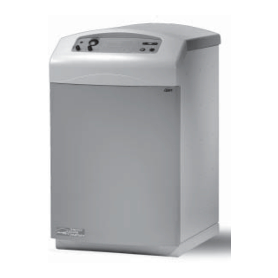
1 - PRODUCT DESCRIPTION Standard options available from Monitor include: Model FCX oil fired heating system utilizes a sealed combustion • Coaxial balanced flue system components for connection to system that operates at a temperature at which the flue products the heating system to provide venting of the flue products and will condense. -
Page 3: 2-Designation Of Components
INTRODUCTION 2 - DESIGNATION OF COMPONENTS 1) Control Panel 2) Control Panel Cover 3) Safety Pressure Relief Valve 4) Condenser 5) Manual Mixing Valve 6) Combustion Product Pressure Test Point 7) Condenser Inspection Port 8) Condensate Drain View from above 9) Drain Cock Front View 10)Burner Air Inlet Pipe... -
Page 4: Fcx Installation And Service Manual
Location and routing of water lines is, of • Remove the front panel attachment screws (P), then pull the course, a significant part of the choice. While Model FCX can be front panel (J) outward towards you at the top to free it from installed in an enclosure such as a closet, ventilation or other the attachment clips. -
Page 5: Flue Connections And Routing
Since the FCX is a condensing heating system , flue products exiting the unit are relatively low temperature, typically from 120 - 212 °... - Page 6 15 and 16 or as dictated by local codes. • Do not place the flue terminal less than 6.56 ft. (2 m) from Option: Straight Horizontal Flue Kit a ventilation hole or opening in a building. NOTE: This is an FCX INSTALLATION AND SERVICE MANUAL...
- Page 7 INSTALLATION Angled Balanced Flue Configuration Fig. 18 Fig. 16 Options: Condensate Tee 3 Concentric extensions 2 45 deg concentric elbows 1 concentric vertical terminal 1 sleeve tile roof flange Use Condensate Tee 1 roof plate for lengths over 6ft Adjustable supports as needed 1 ft minimum above max.
-
Page 8: Alternative Flue Connections
2210 4.33” (110) propellants, household cleaning products, etc. The FCX heating system is a condensing heating system , which Should be used on the end of 110 mm piping run means that the combustion products from the appliance are discharged at low temperature (120° to 212°F) and saturated with humidity. - Page 9 16.4 feet and the Beckett be used on lengths of 15 to a maximum of 36 feet. 45 degree Polypropylene Elbows The Beckett NX burner adapted for use on the FCX must have Fig. 31 the following specifications: The oil line heater is standard with the burner.
-
Page 10: Condensate Drain Connection
Water circuit connections are made in the back of the unit utilizing the four 1" male pipe thread couplings provided or using other adapters provided. The FCX can be connected to various comfort heating water systems as well as to a domestic hot water heating system if desired, observing that: •Water circulating pumps provided in the various circuits must... - Page 11 INSTALLATION Various typical water circuits are Heating system illustrated below : Pressure gauge Connection to a single heating circuit C1 = Radiator circuit, Baseboards, Radiant Panels Fig. 35 or Fancoils VM1 1 circuit mixer valve Dc1 1 circuit heating outlet Rc1 1 circuit heating return Heating system...
-
Page 12: Electrical Connections
24 volt, NEC class 2 for connection to a room thermostat. C. Do not use the internal transformer to power any external system components such as a zone valve. FCX INSTALLATION AND SERVICE MANUAL... -
Page 13: Fuel Oil Supply Connections
INSTALLATION - START UP AND OPERATION UPPER LEFT REAR CORNER OF UNIT (Facing rear of There are three 7/8" holes in the right rear of the unit. Mount a unit) Listed 2 x 4 inch, “HandiBox” type junction box vertically over the lower left hole (facing the rear of the unit) in such manner Fig. -
Page 14: Adjusting The Oil Burner
To gain access to the inside of the unit, first remove the control panel cover by grasping it on both sides and pulling valve caps as the valve handle. FCX INSTALLATION AND SERVICE MANUAL... -
Page 15: Cleaning The System Shell
MAINTENANCE 3 - BURNER MAINTENANCE 1 - CLEANING THE HEATING SYSTEM SHELL • Remove the screws (B) from the cast-iron heating system Once adjusted properly, regular maintenance of the oil burner shell cover (C) is not generally required. A routine examination of the burner •... -
Page 16: Combustion Product Flue
System load: Radiant, high temperature, DHW. Total BTU readjusted clockwise or the burner is rewired for a post purge. requirement A faulty water temperature control can also cause a shutdown. FCX INSTALLATION AND SERVICE MANUAL... -
Page 17: Monitor Products, Inc. ("Mpi") Limited
4) Replacement parts beyond the balance of the original warranty period. As part of its policy of continuous product improvement, Monitor Products, Inc. reserves the right to make changes without notice COPYRIGHT © 2007 MONITOR PRODUCTS, INC. www.monitorproducts.com... -
Page 18: Fcx Parts Breakdown
PARTS BREAKDOWN V I I P A R T S B R E A K D O W N FCX INSTALLATION AND SERVICE MANUAL... - Page 19 2317 SEALING AFM34D 30X21X3 (MALE) 2377L HEATING RETURN 1. CIRCUIT LONG BOLT (PVC) 2378 HEATING FLOW 2. CIRCUIT BAFFLE PLATE F400-F E/FEA-FCX 2318 SEALING ON CONDENSER FLANGE (250X200X1,5) 2379 HEATING FLOW DISK FOR ISOLATION (KERLANE) 2380 HEATING SYSTEM SHELL RETURN...
- Page 20 UPPER FASTENER FOR THE RELAY 2351 SAFETY THERMOSTAT 110 CAP 2356 FUSE 6.3AMP 5X20 1,5M TG400 2358 WIRING FOR FCX 2352 SAFETY THERMOSTAT 120 CAP 1,5M TG400 2359 ELECTR. CONTROL BOX + CABLE * NOT SHOWN ON THE DRAWING FCX INSTALLATION AND SERVICE MANUAL...
Need help?
Do you have a question about the FCX and is the answer not in the manual?
Questions and answers