
Related Manuals for Enco 31(BS)

Summary of Contents for Enco 31(BS)
- Page 1 MILLING \ DRILLING MACHINE Enco 105-1110 Enco 105-1300 w/ Downfeed MODEL 31(BS) / 31N2F(BS) / 25 INSTRUCTION MANUAL 31-100827-R4...
- Page 2 WARNING Some dust created by power sanding, sawing, grinding, drilling, and other construction activities contains chemicals known to the State of California to cause cancer, birth defects or other reprodrctive harm. Some examples of these chemical are: ‧Lead from lead-based paints. ‧Crystalline silica from bricks, cement and other masonry products.
-
Page 3: Table Of Contents
Table Of Contents Page No 1 Overall Aspect ………………………………………………………………… 2 2 Safety Rules For tools ………………………………………………………… 3 3 Specification …………………………………………………………………… 5 4 Features ……………………………………………………………………..… 6 5 Delivery & Installation …………………………………………………….. 6 6 Minimum Room Space For Machine Operation …………………………… 8 7 Use Of Main Machine Parts ……………………………………………….…... -
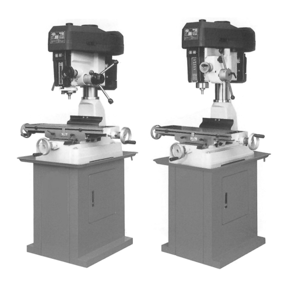
Page 4: Overall Aspect
Overall Aspect - - 2... - Page 5 WARNING: FAILURE TO FOLLOW THESE RULES MAY RESULT IN SERIOUS PERSONAL INJURY As with all machinery there are certain hazards involved with operation and use of the machine. Using the machine with respect and caution will considerably lessen the possibility of personal injury.
- Page 6 hand frees both hands to operate tool. 4. USE RECOMMENDED ACCESSORIES. Consult the owner's manual for recommended accessories. The use of improper accessories may cause hazards. 5. AVOID ACCIDENTAL STARTING. Make sure switch is in “OFF” position before plugging in power cord. C.
-
Page 7: Specification
1.SPECIFICATION MODEL 31(BS) / 31N2F(BS) Drilling capacity 32mm(1 ") 25 mm (1") Face mill capacity 76mm(3") 64 mm (2-1/2") End mill capacity 20mm(3/4") 13mm (1/2") Spindle nose to column surface 170mm(6-3/4") 170mm(6-3/4") Max. distance spindle nose to table 430mm(16-7/8") 325 mm(12-3/4") Spindle taper M.T.3 R-8 M.T.3 R-8... -
Page 8: Features
Tools selection & proper material range Tool type Tool material Work piece material End mill Non-iron material steel iron TUNGSTEN CARBIDE Cast iron non-iron material Face mill TUNGSTEN CARBIDE Non-iron material steel iron Light material Drilling Non-iron material steel iron Light material Tapping HSS Non-iron material steel iron... - Page 9 Fig. B Installation: (1) BE SURE all locks of head-stock & column are tighten before operation. (2) ALWAYS Keep proper footing & balance while moving this 300kgs machine. And only use heavy duty fiber belt to lift the machine as per Fig. A. (3) KEEP machine always out from sun, dust, wet, raining area.
-
Page 10: Minimum Room Space For Machine Operation
4. MINIMUM ROOM SPACE FOR MACHINE OPERATION For 31/31N2F For 25 5. USE OF MAIN MACHINE PARTS (See Fig. l) (1) To raise and lower the head by head handle. (2) Equipped with an electric switch for tapping operation clockwise or counterclockwise. (3) To adjust the quick or slow feeding by feed handle. -
Page 11: Precaution For Operation
6. PRECAUTION FOR OPERATION Check all parts for proper condition before operation; if normal safety precautions are notice carefully, this machine can provide you withstanding of accurate service. (1) Before Operation (a) Fill the lubricant. (b) In order to keep the accurate precision, the table must be free from dust and oil deposits. (c) Check to see that the tools are correctly set and the work-piece is set firmly. -
Page 12: Adjusting Table Slack And Compensate For Wear
QUILL RETURN SPRING ADJUSTMENT: Spring tension for return of spindle, after hole drilling, has been pre-set at the factory. No fur- ther adjustment should be attempted unless absolutely necessary. Adjustment will probably be required if a multiple drilling or tapping head is used. If adjustment is necessary, loosen lock screw while holding. -
Page 13: Clamping /Table Base And Machine Base
8. CLAMPING, TABLE BASE, AND MACHINE BASE (see Fig. 3) (1) When milling longitudinal feed, it is advisable to lock the cross feed table travel to insure the accuracy of your work. To do this, tighten the small leaf screw located on the right side of the table base. -
Page 14: To Change Tools
12 SPEEDS BELT 12 SPEEDS BELT 50Hz 60Hz 50Hz 60Hz 3-5 1000 1200 4-6 1250 1500 2-5 1350 1600 3-6 1900 2300 4-7 2500 3000 Table .1 For 31/31N2F For 25 10. TO CHANGE TOOLS (1) Removing Face Mill or Drill Chuck Arbor Loosen the arbor bolt (see fig. -
Page 15: Tapping Equipment
End Mills Cutter Arbor Taps Collets Adapters and Sleeves 13. TAPPING EQUIPMENT This machine can be equipped with an electric switch for tapping operation clockwise or counter-clockwise, and the working depth also can be adjusted by the limit switch. (Electric switch will be installed according to your requirement, and you must pay the cost only.) 14. -
Page 16: Maintaining
15. SPECIFICATION OF T-SOLT The size of T-Solt on table as Fig 6: For 31/31N2F For 25 16. MAINTAINING That's easier to keep machine in good condition or best performance by means of maintaining it at any time than remedy it after it is out of order. (1) Daily Maintenance (by operator) (a) Fill the lubricant before starting machine everyday. -
Page 17: Trouble Shooting
on belts or other rubber parts. (2) After cleaning, coat all possible rusted surface with a light lubricant. Lubricate all points in Fig.1. with a medium consistency machine oil. (4) Lubricating points as shown in arrows. 18. TROUBLE SHOOTING (1) No running after switch on: (a) Main switch interruption while volts irregular - Adjust input voltage and draw back the main switch. - Page 18 (b) Spindle loosening up and down - Make two of inner bearing covers on the top tight each other. Do not over-tighten two inner bearing covers with the taper bearing; it is ok as long as no gap between them. (c) The gap of taper sliding locate too wide - Adjust the tension of bolt in proper.
- Page 19 (13) Drill leads off: (a) No drill spot. – Center punch or center drill work-piece. (b) Cutting lips on drill off center. – Regrind drill. (c) Quill loose in head. – Tighten quill. (d) Bearing play. – Check bearings and reseat or replace if necessary. (14) Excessive drill run-out or wobble: (a) Bent drill.
-
Page 20: Circuit Diagram
CIRCUIT DIAGRAM... - Page 21 CIRCUIT DIAGRAM...
- Page 22 CIRCUIT DIAGRAM...
- Page 23 -21-...
- Page 24 -22-...
- Page 25 -23-...
-
Page 26: Parts Lists
PARTS LIST MODEL NO.31 CODE NO PART NO DESCRIPTION SPECIFICATION QTY NOTE 6511 Head Body 6101 Chuck Arbor Bolt MT3 M10xP1.5 6101-1 Chuck Arbor Bolt MT3 M12xP1.75 6101-2 Chuck Arbor Bolt MT3 W3/8"-16 6101-3 Chuck Arbor Bolt MT3 W1/2"-12 6101-4 Chuck Arbor Bolt R8 W7/16"-20 6101-5... -
Page 27: Parts List
PARTS LIST MODEL NO.31 CODE NO PART NO DESCRIPTION SPECIFICATION QTY NOTE 6121-5 Chuck Arbor R8 7/16"-20 JT3 6121-7 Chuck Arbor MT3 M12-B16 6121-9 Chuck Arbor MT3 M12 B18 6121-10 Chuck Arbor MT3 M10- B16 6122-3 Chuck Arbor NT30 6120 Cutter Arbor 25.4 M10xP1.5 6120-1... - Page 28 PARTS LIST MODEL NO.31 CODE NO PART NO DESCRIPTION SPECIFICATION QTY NOTE MHP243 split pin SSP5 S732 Cross Round Head Screw 3/16"x3/4"L 61103S Spring Cover Asbly W202 Spring Washer 1/4"x1"x1.5t W005 Washer 1/4" W202 Spring Washer 1/4"x1"x1.5t S471 Hex. Socket Head Screw 1/4"x5/8L 6559 Worm Shaft...
- Page 29 PARTS LIST MODEL NO.31 CODE NO PART NO DESCRIPTION SPECIFICATION QTY NOTE W016 Washer 5/16"x28x3t S019 Hex. Head Screw 5/16"x1-1/2"L 6173AS Inter Pulley Asbly N008 Hex. Nut 5/8" 6170DS Motor Pulley Set BB033 V-Belt B-33 BB042 V-Belt B-42 6577 Wire Relief Retainer S017 Hex.
- Page 30 PARTS LIST MODEL NO.31 CODE NO PART NO DESCRIPTION SPECIFICATION QTY NOTE 6223S Table Nut Set 31\31L Metric 6223-1S Table Nut Set 31\31L Inch 6224S Table Screw Asbly 31 Metric 6224-1S Table Screw Asbly 31 Inch 6224-2S Table Screw Asbly 31L Metric 6224-3S Table Screw Asbly...
- Page 31 -29-...
- Page 32 -30-...
- Page 33 -31-...
- Page 34 -32-...
- Page 35 -33-...
- Page 36 PARTS LIST MODEL NO.31N2F CODE NO PART NO DESCRIPTION SPECIFICATION QTY NOTE 291045 Head Body 6101 Chuck Arbor Bolt MT3 M10xP1.5 6101-1 Chuck Arbor Bolt MT3 M12xP1.75 6101-2 Chuck Arbor Bolt MT3 W3/8"-16 6101-3 Chuck Arbor Bolt MT3 W1/2"-12 6101-4 Chuck Arbor Bolt R8 W7/16"-20 6101-5...
- Page 37 PARTS LIST MODEL NO.31N2F CODE NO PART NO DESCRIPTION SPECIFICATION QTY NOTE 6121-5 Chuck Arbor R8 7/16"-20 JT3 6121-7 Chuck Arbor MT3 M12-B16 6121-9 Chuck Arbor MT3 M12 B18 6121-10 Chuck Arbor MT3 M10- B16 6122-3 Chuck Arbor NT30 6120 Cutter Arbor 25.4 M10xP1.5 6120-1...
- Page 38 PARTS LIST MODEL NO.31N2F CODE NO PART NO DESCRIPTION SPECIFICATION QTY NOTE 39-5 HB111 Oil Ball 1/4" S404 Hex. Socket Head Screw 1/4"x3/4"L 6158S Head Handle Set 6027-1S Head Asbly 6196SA Front Cover Plate Asbly S701 Cross Round Head Screw 1/4"x1/2"L 6169E Belt Cover...
- Page 39 PARTS LIST MODEL NO.31N2F CODE NO PART NO DESCRIPTION SPECIFICATION QTY NOTE Switch 291022AS Gear Box Assembly 401-1 291022B Gear Box 401-2 CA6003ZZ Bearing 6003ZZ 401-3 2450082A Change Gear Lever 401-4 2450084B Twisted Spring 401-5 HP006 ∮3x10L 401-6 2450083A Speed-Changing Key 401-7 2450089A Bushing Bracket...
- Page 40 PARTS LIST MODEL NO.31N2F CODE NO PART NO DESCRIPTION SPECIFICATION QTY NOTE 401-42 291024A Worm Base 401-43 W202 Spring Washer 1/4" 401-44 S404 Hex. Socket Head Screw 1/4"x3/4"L 401-45 HCS06 C-Retainer ring 291032A Gear Box Cover 291029AS Pinion Shaft Assembly 403-1 2450048 Worm Gear Cover...
- Page 41 PARTS LIST MODEL NO.31N2F CODE NO PART NO DESCRIPTION SPECIFICATION QTY NOTE 291051AS Micro Adjusting Indicator Set Inch 6142BS Handwheel Assembly 290110S Sub-Pulley Set 290114 Round Belt ∮8x679 290086 Plastic Round Knob HW016 Washer 5/16"x23x2t HS241 Hex. Socket Head Screw M8x12L 291057 Rubber Plate...
- Page 42 PARTS LIST MODEL NO.31N2F CODE NO PART NO DESCRIPTION SPECIFICATION QTY NOTE S414 Hex. Socket Head Screw 5/16"x1"L S418 Hex. Socket Head Screw 5/16"x2-1/4"L 6215S Acme Nut Asbly Metric 6215-1S Acme Nut Asbly Inch 6606 Swivel Base 6605S Acme Screw Asbly Metric 6605-1S Acme Screw Asbly...
- Page 43 -41-...
- Page 44 -42-...
- Page 45 -43-...
- Page 46 PARTS LIST MODEL NO.25 CODE NO PART NO DESCRIPTION SPECIFICATION QTY NOTE 7111 Head Body 7101 Chuck Arbor Bolt MT3 M10xP1.5 7101-1 Chuck Arbor Bolt M12xP1.75 7101-2 Chuck Arbor Bolt W3/8"-16 7101-3 Chuck Arbor Bolt W1/2"-12 7101-4 Chuck Arbor Bolt W7/16"-20 7102B Spindle Locknut...
- Page 47 PARTS LIST MODEL NO.25 CODE NO PART NO DESCRIPTION SPECIFICATION QTY NOTE 7120 Cutter Arbor MT3 M10xP1.5 7120-1 Cutter Arbor MT3 M12-∮22 7120-2 Cutter Arbor MT3 W3/8"-16 7120-3 Cutter Arbor MT3 W1/2"-12 7120-4 Cutter Arbor R8 W7/16"-20 N005 Hex. Nut 3/8"...
- Page 48 PARTS LIST MODEL NO.25 CODE NO PART NO DESCRIPTION SPECIFICATION QTY NOTE W002 Washer 1/2"x7/8"x2t 7124 Handle Rod 7127 Screw Key N005 Hex. Nut 3/8" 6162 Spring 7163 6179 Rubber Collar 7152 Head Body Fix Bolt 1/2"-172L W001 Washer 1/2"x1-1/4"x3t N001 Hex.
- Page 49 PARTS LIST MODEL NO.25 CODE NO PART NO DESCRIPTION SPECIFICATION QTY NOTE 7186B Milling Cutter ∮22 6187 Chuck 1/2"-JT6 6187-1 Chuck 1/2"-B16 For CE only 7104-5 Protective Plate(For CE Only) For CE only HS527 Cross Round Head Screw M6x10L For CE only 7104-4 Protective Plate(For CE Only) Option...
- Page 50 PARTS LIST MODEL NO.25 CODE NO PART NO DESCRIPTION SPECIFICATION QTY NOTE S418 Hex. Socket Head Screw 5/16"x2-1/4"L 6215S Acme Nut Set Metric 6215-1S Acme Nut Set Inch 12206 Swivel Base 7205S Acme Screw Set Metric 7205-1S Acme Screw Set Inch 7208 Column Base...
- Page 51 -49-...
- Page 52 PARTS LIST MODEL NO. 31BS CODE NO PART NO DESCRIPTION SPECIFICATION QTY NOTE 6628 Table 6628-1 Table 6229 Fixed Block 6230 Movable Fixed Ring S402 1/4"x1/2"L Hex. Socket Head Screw HB111 1/4" Oil Ball 6601CS Table Handle Wheel Set 6620 ∮17 Table Clutch HP048...
- Page 53 PARTS LIST MODEL NO. 31BS CODE NO PART NO DESCRIPTION SPECIFICATION QTY NOTE 6656 ∮6x230L Oil Hose 6657 ∮6x330L Oil Hose 6658 ∮6x140L Oil Hose 6659 ∮6三孔 3 Way Connector HB501 1/8" Oil Ball HS231 M6x25L Hex. Socket Head Screw 6660 PT1/8x90度∮6 Oil Hose Coupler...
- Page 54 -52-...
- Page 55 PARTS LIST MODEL NO. DRO NOTE CODE NO PART NO DESCRIPTION SPECIFICATION 670032 Radial Arm 670044 Cover 670046 Plum Screw 5/16'x1"L S482 Hex. Socket Head Screw 1/2"x2-3/4"L HB811 1/2" W035 Washer ∮1/2"x∮25x1.8t 670033 Radial Arm Bracket S401 Hex. Socket Head Screw 1/4"x1"L W037 Washer...
- Page 56 MANUFACTURER: ADDRESS: SERIAL No.: PLEASE WRITE DOWN THE SERIAL NO. ON THIS BLOCK FROM THE NAME PLATE AFTER YOU RECEIVE THIS MACHINE.
Need help?
Do you have a question about the 31(BS) and is the answer not in the manual?
Questions and answers
What is the wiring from the rotory switch to motor? on a 31n/31bs