Table of Contents
Advertisement
Suitable for
Electric
or
I.C. Engine
Power
Congratulations on the purchase of your
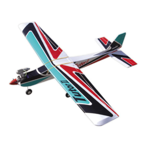
Irvine Tutor 40 II Radio Control Model
Aircraft. Please take some time to carefully
read these instructions before assembly
and your first flights.
The Irvine Tutor 40 II is an ideal first model
or aileron trainer she will reward you with
many hours of superb flying and enjoyment!
Tutor 40 II Specification:
Wingspan .........................................62 3/8" (1635mm)
Length ..............................................47 1/4" (1200mm)
Engine .......................... .40-.46 2-Stroke (Not included)
Motor ....................................... 700 watt (Not included)
INSTRUCTION MANUAL
Items required to complete the Tutor 40 II
Glow Engine version Requires
.40-.46 2-Stroke engine
4 Channel Proportional Radio Control System
Model Engine Fuel
Model Engine Starter and Glow Plug Battery (for Glowstart)
Hand Tools and Adhesive
Fuel tubing and propeller suitable for engine
Electric Conversion Requires
KMS Quantum 4120/05 Brushless Motor
Arrowind 60amp Electronic Speed Controller (ESC)
Intellect 4S 4000 25C Li-Po Flight Battery
4 Channel Proportional Radio Control System
12 x 6 Propeller
Part No: A-IRVTUT40/2
Advertisement
Table of Contents

Summary of Contents for Irvine Tutor 40 II
- Page 1 .40-.46 2-Stroke engine 4 Channel Proportional Radio Control System The Irvine Tutor 40 II is an ideal first model Model Engine Fuel or aileron trainer she will reward you with Model Engine Starter and Glow Plug Battery (for Glowstart)
- Page 2 Please carefully read and follow all instructions included with this aircraft, your radio control system and any other components purchased seperately. TOOLS AND MATERIALS REQUIRED To complete the assembly of the Tutor 40 II, you will require a few hand tools and suitable adhesives: • Non-permanent marker pen • Clear tape or masking tape • Modelling knife...
- Page 3 (1.5mm) four holes for the mounting screws supplied with your servo. Now screw the servo in position noting the orientation. Take care not to drill into the servo lead. 5.1. Fit grommets and ferrules to the aileron servo 5.2. Trim the mount for the servo lead’s exit 5.3. Pilot drill the mounting holes 5.4. Screw the servo in position Irvine Tutor...
- Page 4 Make sure that you do not remove any wood from the slots as this will affect the alignment of the tail and fin. 9.1. Trim the covering from the fin slot 9.2. Trim the covering from the tail slots Irvine Tutor...
- Page 5 Trial fit the fin in its slot. With correctly aligned, mark the shape of the fuselage on both sides of the fin using a water- soluble/non-permanent felt pen. Mark the shape of the fin extension on the fuselage too. 14.1. Mark the shape of the fuselage on the fin 14.1. Mark the shape of the fin on the fuselage Irvine Tutor...
- Page 6 Slide a wheel on, then fit a second collet, ensuring that the wheel is free to spin. Add a drop of cyano to each retaining screw to secure 18.1. Fit a collet to the axle 18.2. Retain the wheel with a second collet Irvine Tutor...
- Page 7 21.5. Clip off any excess Stage 22 The rudder horn is fitted in exactly the same way as the elevator. Note that it should be located on the left hand side of the rudder (when viewed from 22.1. Position the horn as shown 22.2. Screw in place Irvine Tutor...
- Page 8 Re-connect the clevis (centre 26.1. Disconnect the clevis hole in the horn) and ensure that the elevator is level with the elevator servo at its neutral position then snap the clevis closed. Slide the tubing back over the clevis for additional security. 26.3. Re-connect the clevis with the tube to secure Irvine Tutor...
- Page 9 Slide the tubing back over the clevis for additional security. The Irvine Tutor 40 II is suitable for both Electric Motors and I.C. Engines. The following sections cover I.C. Engine installation and Electric Power.
- Page 10 Slip the throttle pushrod connector over the pushrod and re-fit the throttle servo horn. Do not 4.3. Slide connector over the pushrod then fully tighten the grubscrew yet as the throttle is adjusted later. re-fit the horn Irvine Tutor...
- Page 11 Use your transmitter’s end point adjustment - EPA/ATV - (or adjust mechanically) so that the throttle opens and closes as shown in the diagrams below (A) Low Throttle (B) Mid Throttle (C) High Throttle HIGH Throttle Throttle Throttle Stick Stick Stick Position Position Position Irvine Tutor...
- Page 12 5.1. Motor wires go through the bulkhead Stage 6 Mount the ESC (Electronic Speed Controller) to the fuselage side using adhesive foam tape. The battery is retained in the tray by the Velcro straps provided. It is a good idea 4.1. Fit the spinner backplate and propeller 6.1. Attach your ESC with double sided tape Irvine Tutor Irvine Tutor...
- Page 13 Before starting the final set-up of the Tutor 40 II, switch on the radio and ensure that all trims are in their neutral positions. Check that the ailerons, elevator and rudder are centred.
- Page 14 ELEVATOR UP ELEVATOR DOWN Stage 37 For the Tutor 40 II to fly well, its control surfaces need to move the correct amount. Too little movement and the model will be slow to react to your commands;...
- Page 15 I.C. engine power. FLYING THE TUTOR 40 II Always fly the model in a safe and suitable location, away from houses, people and power Stage 39 lines.
- Page 16 Ripmax Ltd. guarantees this product to be free from manufacturer’s defects in both material and workmanship at the date of purchase. This guarantee does not cover faults arising from misuse or accident and the guarantee does not cover damage or malfunction caused by negligence, misuse, accident, unauthorised repair or modification.
Need help?
Do you have a question about the Tutor 40 II and is the answer not in the manual?
Questions and answers