
Related Manuals for Dali DVR-404DB

Summary of Contents for Dali DVR-404DB
-
Page 1: Digital Video Recorder
Stand alone Multi- channel Digital Video Recorder User Instruction Manual VERSION 1.2 Before attempting to connect or operate this product, please read these instructions carefully and save this manual for future use. - Page 2 Warning This apparatus must be earthed. Apparatus shall be connected to a mains socket outlet with a protective earthing connection. The mains plug or an appliance coupler shall remain readily operable. To prevent fire or electric shock hazard, do not expose this apparatus to rain or moisture. The apparatus should not be exposed to dripping or splashing and that no objects filled with liquids, such as vases, should be placed on the apparatus.
-
Page 3: Limitation Of Liability
Limitation of liability This publication is provided “as is” without warranty of any kind, either express or implied, including but not limited to, the implied warranties of merchantability, fitness for any particular purpose, or non-infringement of the third party’s right. This publication could include technical inaccuracies or typographical errors. - Page 4 INSTALLATION & SAFEGUARDS Please read these instructions before operating the unit. Installation. Refer all work related to the installation of this product to qualified service personnel or system installers. Avoid the following locations for installation. * Places exposed to direct water, moisture, or sunlight directly *...
-
Page 5: Before You Start
(Tightening torque: Approx. 0.49 N m {5 Kgf cm}) Avoid rapid changes of the temperature/humidity to prevent condensation. (Acceptable change: within 15℃/h{59℉/h}) Before You Start. 1. Do not attempt to open or remove the covers. This may expose you to dangerous voltage or other hazards. 2. -
Page 6: Important Safety Instructions
Important safety instructions Read and keep these instructions. Heed all warning. Do not connect this unit to an outlet to which appliances with high power consumption such as an air conditioning or a copy machine is already being connected. Do not use this apparatus near water. To reduce the risk of electric shock, do not remove cover (or back). -
Page 7: Table Of Contents
Content Chapter I Introduction............................9 Chapter II System Installation ..........................11 Section 1 Operating Environment ........................11 Section 2 HDD Installation ..........................11 Section 3 Back panel ..........................14 Back panel of typeⅠ 4 channel model (page.6) ..................14 Back panel of type Ⅱ model (page.6) ....................15 Back panel of typeⅠ... - Page 8 Recording Auto Overwrite ........................41 Section 8 Recording ............................41 Record Parameter Setup .......................... 41 Manual Recording ........................... 42 Schedule ..............................43 Recording Alarm Setup..........................44 Alarm Elimination ........................... 46 Section 9 Playback/Backup .......................... 46 Playback ..............................46 Backup ..............................48 Section 10 Network Setup ..........................
- Page 9 Local Setup .............................. 69 Advance Setup ............................69 Remote control ............................71 Chapter Ⅵ Frequency Asked Questions ......................72 Appendix 1 HDD Capability Calculate ......................73...
-
Page 10: Chapter I Introduction
Chapter I Introduction Thank you for choosing our stand alone Digital Video Recorder System. Please pay attention to these instructions before using the DVR. The manual explains the operation modes and performance criteria of our stand alone H264 DVR. Please read the manual carefully before using the DVR, and install the system according to the instructions. Mainframe software is subject to renewal without prior notice. -
Page 11: Product Introduction
Product Introduction 1. Compress Support PAL/NTSC video format, 25FPS (PAL), 30 FPS (NTSC), H.264; Support both variable bitrate and variable frame rate. Support dual stream, video config setting. Support motion detection, video shelter area. Support OSD, date and time display. 2. -
Page 12: Chapter Ii System Installation
Chapter II System Installation Section 1 Operating Environment The following operating environment for this DVR must be adhered to: DVR Operating Environment Items Instructions Electromagnetism DVR’ complies with National Electromagnetism Radiation Standards. Temperature -10℃ to 55℃ Humidity 10 % to 95 % Power Supply 12V volts D.C. - Page 13 Fig. 1 TypeⅠ 16 channel model and type Ⅲ model(page.6) should be removed as fig.2. Fig. 2 2. Remove HDD mounting bracket. 3. Fit HDD onto bracket using supplied mounting screws. 4. Replace HDD mounting bracket. 5. Connect the ATX power cable to the power connection on the HDD. Pay attention to the correct orientation.
- Page 14 Fig. 4 After installed, typeⅠ 16 channel model (page.6) should be as fig.5: Fig. 5 8. Replace the top of the DVR enclosure. Note: Please fix the screws at the back side of DVR before the flank side while assembling the lid. NOTE: Please format the hard disk before record.
-
Page 15: Back Panel
Section 3 Back panel Back panel of typeⅠ 4 channel model (page.6) Fig. 6 Interface Connection Description (A IN) Audio input connect simulate audio input device, standard BNC interface (V IN)Video input connect simulate video input device, standard BNC interface (A OUT)Audio output connect audio output device, standard BNC interface Active device is requested while exporting audio... -
Page 16: Back Panel Of Type Ⅱ Model (Page.6)
Back panel of type Ⅱ model (page.6) Fig. 7 Interface Connection Description 1-2 (V IN)Video input connect simulate video input device, standard BNC interface (A IN) Audio input connect simulate audio input device, standard BNC interface (V OUT) Video output connect monitor, local video signal output RS485 port connect RS485 device, details refer to “Section 5... -
Page 17: Back Panel Of Typeⅰ 16 Channel Model (Page.6)
Back panel of typeⅠ 16 channel model (page.6) Fig. 8 Number Function Description Power Supply Input(AC IN) 110/220V AC Voltage Input Video Input(V IN) Connect analog video input device, standard BNC port Normal editions are for audio input Normal edition DVR connect to audio input device, standard BNC connector. - Page 18 Fig. 9 T+, T- are senders of RS485, connect to Rx+ and Rx- of PTZ or dome. Details refer to “Section 5 PTZ (pan, tilt and zoom) control connection”. Note: RS485(2) is set for PTZ control. R+, R- are receivers of RS485, connect to keyboard. This DVR can only use 485(1) port for keyboard. Remark 2 RS485 matched resistance Open the cover, there is a 2*4 pin header (SW1) between Network port and RS485 port.
-
Page 19: Back Panel Of Type Ⅲ Model (Page.6)
Back panel of type Ⅲ model (page.6) Fig. 10 Interface Connection Description A/D capture input (optional) Alarm read analogue input, and it can connect sensor Video Input (V IN) BNC input Audio Input (A IN) BNC input power supply(DC 12V/5A) 12V volts D.C. -
Page 20: External Alarm In/Out Connection
adapt to USB mouse. Video Output(V OUT) Connect monitor, local video output Audio Output(AOUT) connect audio output device, standard BNC interface Section 4 External alarm in/out connection Alarm in The alarm input is NO/NC input. Please connect signal port to any of 1-16 port and GND port. For NO input please setup “Main Menu—Rec. -
Page 21: Ptz (Pan, Tilt And Zoom) Control Connection
Fig. 13 Note: 24V DC (1A), 120V AC (1A) voltage and current are suggested. Section 5 PTZ (pan, tilt and zoom) control connection TypeⅠ 4 channel model and type Ⅱ models’ (page.6) PTZ linkage should be as follows: Fig. 14 A and B ends of RS485 can be connected with the Rx+, Rx- on PTZ or High Speed Dome. -
Page 22: Section 6 Intercom
Note: Please do not connect RS485 and RS232 simultaneously. Section 6 Intercom Fig. 16 In the above illustration, the up icon is an ear phone socket and the down icon is a MIC phone socket. After the DVR_WEB or Netclient software has connected with the host, and also the ear phone and MIC phone be connected. -
Page 23: Chapterⅲ Dvr Operation
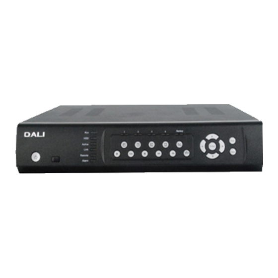
ChapterⅢ DVR Operation Section 1 DVR Front Panel TypeⅠ 4 channel model and type Ⅱ model (page.6) Fig. 18 Name specification Power switch IR receiver Working indicator, flashing after boot normally. HDD indicator, flashing when access HDD date. ACTIVE Network communication indicator, flashing when network is connected. LINK Network connection indicator, lighting constantly when network is connected. -
Page 24: Typeⅰ 16 Channel Model (Page.6)
2. Motion and Shelter area enable 3. Select pane “1” in cover area setting 1. For 8 CH series DVR, Select 1-split, 4-split,9-split display; for 4 CH series DVR, select 1 split, 4 split display 2. Motion and Shelter area disable 3. - Page 25 ALARM Alarm indicator, flashing when alarm is activated 1—16 1-16ch record indicator(it lights when corresponding channel is recording) 1. Direction key ‘UP’; 2. Display the status column in preview mode 1. Direction key ‘DOWN’ 2. Hide the status column in preview mode Direction key ‘LEFT’;...
-
Page 26: Type Ⅲ Model (Without Lcd) (Page.6)
Entry “Playback Dialog” interface Split screen mode switch Reserved for future use USB port (support USB2.0 which adapt to USB storage device) MIC and earphone IR receiver Type Ⅲ model (without LCD) (page.6) Fig. 20 Name specification Power switch IR receiver POWER Power indicator, lighting constantly when connected power HDD indicator, flashing when access HDD date... -
Page 27: Type Ⅲ Model (With Lcd) (Page.6)
Select 1, 4 split display 1. Direction key “UP” 2. Display the status bar in preview mode 1. Direction key “DOWN” 2. Hide the status bar in preview mode Direction key “LEFT” Direction key “RIGHT” ENTER “OK” key “Cancel” key 1. -
Page 28: Ir Remote Device (Optional)
Name specification Power switch IR receiver POWER Power indicator, lighting constantly when connected power Working indicator, flashing after boot normally ALARM Alarm indicator, flashing when alarm is activated HDD indicator, flashing when access HDD date 1-4CH record Corresponding channel record indicator (it lights when corresponding channel indicator is recording) Entry playback and backup interface... - Page 29 Insert the battery, then aim the launch end at the receive end of DVR while using IR remote controller. In the control range, if more than one DVR need to be controlled separately, please press “ID” or “SELECT” button, then input the host address of which DVR need to be controlled and press “OK” or “ENTER” button will realize the function.
-
Page 30: Mouse Operation
Refer to the section of ‘Panel’ for the detailed description of the keys function on remote control unit. Here are the function buttons on the remote control: Buttons Functions PTZ enable switch SETUP Plus 10 Entering “Search dialog” SAVE RETURN Enter the input mode window Section 3 Mouse operation... -
Page 31: Input Mode Introduction
to enter the main menu. Mouse Option *Modify Number Double-click mouse left key to input number or use trolley of mouse to modify number directly. *Modify Character Double-click mouse left key to input character. *Modify Option Choose option with trolley of mouse or in the option box after left click. *Exit Menu Right click to exit menu step by step. - Page 32 “ESC” in the front panel to save and exit. Input mode interface of typeⅠ 16 channel model (page.6): DVR support four input modes: number, Chinese, capital and lowercase letter input. Press to get into input interface on number input box or character edit box as shown in Fig. 24: Fig.
-
Page 33: Chapter Iv System Operation
Chapter IV System operation Section 1 Menu Navigation Fig. 25 Main Menu Sub Menu Function Playback Search recording, playback or backup Setup recording and network transmission resolution, codec type, image General quality, stream bit, frame rate of channels Schedule Schedule recording, Motion, Alarm in, video shelter and video lost alarm time period setup Rec. -
Page 34: Section 2 Surveillance View
Version System firmware version information and MAC Online Check online user information, force kick online user Section 2 Surveillance View Status Bar Scrolling up the or pressing the " " on the front panel, screen will show the status bar as follows: Fig. -
Page 35: Screen Switch
External and alarm (red) Connected in web Screen Switch TypeⅠ 4 channel model, type Ⅱ 4 channel model and type Ⅲ model (with LCD) (page.6): Under the surveillance mode, system defaults 4-screen, press to have the first split screen full screen, press to have the second split screen full screen, press to have the third split screen full screen, press to have the forth split screen full screen. -
Page 36: Section 3 Login And Logout
TypeⅠ 16 channel model (page.6): Under the surveillance mode, press and the system enters single screen mode. “Auto switch” will be displayed on the status column. Press again and the sequence mode will be canceled. The “Auto switch” on the status column will disappear. Section 3 Login and Logout System Login... -
Page 37: System Logout
System Logout Method 1: Enter “Main Menu-Advanced-Maintenance” then select ‘Logout’ to logout the system. Method 2: Set ‘Auto Logout’ as ON in “Main Menu”→ “Advanced”→ “General” and input idle time, then system will auto-lock keyboard if no command input within the time set. Section 4 System Reboot Shutdown... - Page 38 Fig. 29 Move cursor with on the front panel and select item with System Time:Press to get into input interface for time inputting. Time Format:Setting the time format and DST. Please refer Fig. 30. Note: If you need to modify system time please close the record. Fig.
-
Page 39: Time Display
Time Display. Enter “Main Menu-Advanced-Display”. In the interface, when recording or remote monitoring chose, time display or not is selectable. To display time Enter “Set” to adjust display location on the screen. Whenever the Time box and Channel name box are overlapped, the system will separate them automatically. Note: Time position of realtime monitoring screen is unalterable. - Page 40 Fig. 31 Move cursor with on the front panel and select item with Remote Control: When you use IR controller to operate DVR, you must use this address to select DVR. If there are more than one DVR in one place, please define different address for each DVR. The default address is “001”, the value field among 001-255.
-
Page 41: Section 7 Hdd Management
Idle time: Length of time during which no operation is executed. Default Idle time: 5 minute. Screen Saver: This option is special for III type model( with LCD) (page.6) , and it can control LCD display time. DVR will not get into power saving mode if the option is set as 000. And the default value is 5min. VGA Resolution:... -
Page 42: Recording Auto Overwrite
Fig. 33 Press “Ok” to format HDD. Note: 1. Do not format a disk while it is recording. 2. Format a HDD will delete all the data in it. Recording Auto Overwrite Enter “Main Menu-Rec. &Alarm—HDD” to setup ‘Auto Overwrite’ function: whether activate overwrite function when HDD is full. -
Page 43: Manual Recording
Channel Number: choose a channel to setup. Resolution: Options are CIF and D1. Max Bit Rate: If you select VBR, when the video input has great movement, we need to limit the max bit rate. The max bit rate selection has relations with resolution. If you select high resolution, you must select high bit rate. -
Page 44: Schedule
Record: Press this button to start all channels recording. Stop: Press this button to stop all channel recording. Return: Press this button to close the Manual Record window. Schedule Enter “Main Menu-Rec. &Alarm—Schedule” as shown in Fig. 36. Fig. 36 If user need to open the corresponding record or alarm, the effective time should be set in this menu: "ALL"... -
Page 45: Recording Alarm Setup
Set: Press ‘Set’ to save setting temporarily, if need to set multiple recording periods. NOTE: Only press ‘OK’ to save all setting permanently without lost when power is blackout. Press ‘Set’ to save temporarily, all setting will lost when power is off. Click "manage"... - Page 46 minutes. Pre-record Time: Activate pre-record function including “OFF、 5s、 15s、 25s、 30s”. Default pre-record time: OFF. Buzzer Time:Alarm time length when alarm, motion detection, video lost or video shelter is activated. Default length: 5 seconds. Alarm Beep: Beep or not when alarm, motion detection, video lost or video shelter is activated. Default: Off. External Alarm Input Setting Enter “Alarm In”...
-
Page 47: Alarm Elimination
Sensitivity:Select sensitivity of motion detection or video shelter. Option including: Highest, High, Medium, Low, Lowest. Area Setup: Alarm area should also be set to activate motion detection or video shelter though such function was selected. In area setup interface, full screen is the default alarm area. In typeⅠ 4 channel model, type Ⅱ model and type Ⅲ... - Page 48 Fig. 41 Move cursor with on the front panel and select item with From:Set the starting time. CH:If the “CH” channel is selected as 00, files of all channels will be searched. All:Recorded files type. The file type options have “All, Timer, Motion, Alarm, Command, and Manual”. One_CH:Support Max.
-
Page 49: Backup
:1. Pause current video playback. 2. Continue playback from pause mode :Stop current video playback. :Skip to previous section and play automatically. :Jump backward a certain time to play. :Jump forward a certain time to play. :Skip to next section and play automatically. -:Play as 1/2, 1/4 of normal speed. -
Page 50: Section 10 Network Setup
Use a computer which installed “Windows Media Player” and then run “H264ax.exe” according to the hint of installation. After above steps recordings can be played via “Windows Media Player”. More details please refer to “Readme.txt”. PS: Type Ⅲ model’s (page.6) record can be played by Media player directly after backup, and need not to install any other plug-in software. -
Page 51: Pppoe
be identical. Use the Gateway address first.) ETH mode: Could choose “Adaptive”, “Half Duplex 10M”, “Full Duplex 10M”, “Half Duplex 100M” and “Full Duplex 100M”. Default is “Adaptive”. DNS: Please set DNS as local network supplier's IP when DVR is accessed from WAN. Server Port and Server IP: If you set this IP and port, when there is alarm and exception happened, DVR will send information to that host IP. -
Page 52: Section 11 User Management
Fig. 44 User can setup DDNS in this interface and access the DVR through the set domain name. Provider: Could choose “dyndns.org” and “3322.org”. Host name: Domain name that user register. E.g. If the supplier is “dyndns.org”, and the registered domain name is “user.dyndns.org”, you can input “user”... -
Page 53: Add User
into password modify interface, then press“ ”or “ ” on front panel to modify password. Add User When you login as “Admin”, you can add new user. Select “Add” to enter into “Add User” menu as shown in Fig. Fig. 46 Press “... -
Page 54: Rights Setup
password in “Password Setup” interface. Rights Setup When you login as “Admin”, you can setup the rights for new users. Use “ ” and “ ” key to move cursor to the corresponding right items, press “ ” and “ ”... -
Page 55: Section 12 Display Setup
to enter into “System Message” interface as follows and delete it. E.g. the user name is “123” as shown in Fig. 49. Fig. 49 User manages explain: User levels have Administrator and Normal user. Can be set 1 Administrator and 29 normal users; Administrator can modify all users’... -
Page 56: Section 13 Ptz Setup
Move cursor with on the front panel and select item with Channel number: Select one channel for setting. Cover Channel: whether to display current channel or not Activate Shielding:Provide you to mask the sensitive area. Move cursor to “Area Set” and set the area. In the shelter area setup interface, there are four small panes. -
Page 57: Serial Port
Baudrate: Default 9600. Speed: PTZ turning speed. PTZ Addr: Each PTZ has one different address. Default system configuration: 001. Select “More..” to set data bit, stop bit and other parameters: RS-485 parameters: Including baudrate, data bit, stop bit, parity bit, flow control, etc. These parameters must be the same as those of PTZ Protocol. -
Page 58: Ptz Control
Fig. 54 Fig.55 PTZ Port: You should select the “RS485” when the RS485 port is connected to PTZ; And you should select the “RS232” when the RS232 port is connected. When temperature or humidity transducer is connected, user can set the parameter in fig.55. If the display value is inconsistent with the actual situation, user can adjust it by modify coefficient and correction. -
Page 59: Section 14 Restore Defaults Setting
Fig. 57 Choose “Preset” to setup or call the corresponding preset. “001” is an order of preset positions and click “Set” to set a preset position, click “Call” to move PTZ to a preset position; Cruise Setup Choose “Cruise”, and get into the interface as follows: Fig. -
Page 60: Section 15 Information Inquiry
Fig. 60 Move cursor with on the front panel and select item with Select a item to restore default setting. Section 15 Information Inquiry Log Information Enter “Main Menu-Information-Log” as shown in Fig.61. Fig. 61 Move cursor with on the front panel and select item with Input start time and stop time and then move cursor to “Search”... -
Page 61: Version Information
Version Information Enter “Main Menu-Information-Version” as shown in Fig.62. Fig. 62 Check information of current firmware version. User Information Enter “Main Menu-Information-Online” as shown in Fig.63. Fig. 63 List box: Display the remote user name, State and IP address. Use key to move the cursor. -
Page 62: Section 17 Reset
please refer “ChapterⅤ”. Method 2: You can use this function to upgrade the firmware. (1) Create a file with a name of “update” in the USB storage, and copy the firmware file to this directory and rename it with special file name. (page.6) DVR Model typeⅠ... -
Page 63: Chapterⅴ Ie Monitor
ChapterⅤ IE Monitor Section 1 Introduction The DVR can be visited and controlled by IE browser. IE provides the functions, such as remote monitor, local record, PTZ control, Remote control, etc. Section 2 Installation Requirements Requirements for the PC hardware for monitoring, through IE access under the normal condition: CPU: Interl pentium4 2.0GHz and higher Ram: DDR 512MB and higher Video card: independent video card with 64M video memory and higher... -
Page 64: Section 4 Basic Surveillance Operation
Basic Surveillance Operation Section 4 Start Program Input http://10.0.0.124 (suppose host IP: 10.0.0.124) in the IE address bar, after connected, display the initial interface with default English language, the user can set another language through click the “Local Setup”-“Language” at the lower right corner on the main interface. The main interface shown as Fig.69: Fig. -
Page 65: Login/Logout
b) Video user number: support max.24 users at the same time. c) Playback user number: support max.4 users at the same time. Login/logout 1. Click login button at higher right corner on the main interface(Fig69①marks), or right click the video display area anywhere, or click the menu and setup, the system will pop-up the login interface. -
Page 66: Ptz Control
click again, return to the original. Also user can click the shortcut button in the bottom to switch to split screen (1/4/9/16). 3. Image adjust: select the one surveying channel image, the “Picture Adjust” bar is on the right, shows the surveying image status(brightness, hue, contrast, saturation), adjust the image effects on the host and IE web, by adjust this items. -
Page 67: Shortcut Operation Button
4. Light, wiper function: provide lamp and wiper open and shutdown function. The PTZ should support the lamp and wiper function to realize them. 5. Cruise control: in fig69 “ ”icon shows the area of cruise control, cruise including auto cruise and route cruise. -
Page 68: Section 5 Menu Configuration Setup
operate the video display. 4. The audio output will be auto closed temporarily, when open the intercom function, and will return to original after the close the intercom (Fig 74). Fig.74 Adjust the image The mark right on the main interface, is image adjust area. The detail operation please see the above ④... -
Page 69: Info Search
Fig. 75 Info search 1. Click , entry “Information” interface. 2. Log information search: search the log information in the remote DVR according to the time, model. 3. HDD info: check all online HDD, HDD capacity, HDD spare capacity on the host. 4. -
Page 70: Local Setup
Local Setup Click entry “Local Setup” interface, setup local configuration, including: language, stream type, transmit protocol, circular channel quantity, local save route etc. 1. Language selection: provide local IE web language switch and display function. 2. Stream type: select the transmit model, including main stream, sub stream (net transmit code type). The main stream setup in the “Advance Setup-Transfer”. - Page 71 7. Email function: provide the email function that auto send the emails with alarm log, operation log, exception log to the host when triggered. Steps: Select the email function “yes”. Fill out the email address which the email will send to. Select triggered model for email: like alarm, operation or exception.
-
Page 72: Remote Control
Remote control Click entry “Remote Control” interface, could control remote record open /close and system maintain 1. Record control: remote open/close the host record. 2. System maintain: provide DVR system image file update, web software update, remote DVR reboot, restore default (factory default), export Remote system configuration, import remote system configuration, shutdown system and download Player plug-ins. -
Page 73: Chapter Ⅵ Frequency Asked Questions
Chapter Ⅵ Frequency Asked Questions 1. Can not control DVR with IR controller, but it’s normal while using the front panel. Check whether the battery is exhausted. Replace a new battery. Check whether the address of controller is the same as the ID of DVR. If not, please change the address of controller at 000 or input the same ID of DVR. -
Page 74: Appendix 1 Hdd Capability Calculate
control. After activating the control, if one or more problems occur such as channel covered with white lump, control disappear or right click pop-up no menu, please update patches(KB945007 and KB912945) on http:\\www.microsoft.com. 11. Open the IE connect interface, under the XP system, if can not download the subtitle normally, please check the XP system scripting. - Page 75 Information on Disposal for Users of Waste Electronic Equipment (private households) This symbol on the products and /or accompanying documents means that used electrical and electronic products should not be mixed with general household waste. For proper treatment, recovery and recycling, please take these products to designated collection points, where they will be accepted on a free of charge basis.
Need help?
Do you have a question about the DVR-404DB and is the answer not in the manual?
Questions and answers