Table of Contents
Advertisement
Operation Manual
SERIES IZ15E
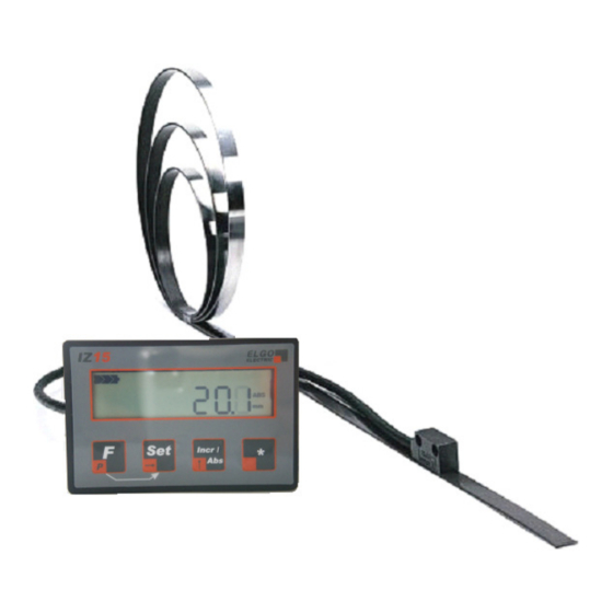
Battery powered Length measuring System
Battery powered Length measuring System
Battery powered Length measuring System
Battery powered Length measuring System
Predestined for the mobile assembly on manual sledges, carriage and back
stop systems
Battery powered indicator
LCD Display
Advertisement
Table of Contents

Summary of Contents for ELGO Electronic IZ15E
- Page 1 Operation Manual SERIES IZ15E Battery powered Length measuring System Battery powered Length measuring System Battery powered Length measuring System Battery powered Length measuring System Predestined for the mobile assembly on manual sledges, carriage and back stop systems Battery powered indicator...
-
Page 2: Table Of Contents
5.1.1 Dimensions Indicator ......................10 5.1.2 Dimensions Sensor ......................10 5.1.3 Accessories ........................11 5.1.3.1 IZ15E-000-3-XX.X-0 ....................11 5.1.3.2 Battery Sets for IZ15E-000-3-XX.X-0 ................ 12 5.1.3.3 IZ15E-000-4-XX.X-0 ....................13 5.2 Technical Data ........................14 6. Installation ........................15 6.1. Qualifications of the Staff ....................15 6.2. -
Page 3: General Information
General Information 1. General Information 1.1. Information Operation Manual The manual contains important information regarding the handling of the indicator. Precondition for safe operation is the compliance with the specified safety and handling instructions. Moreover, observe the existing local accident prevention regulation and general safety rules. Please read the operation manual carefully before starting to work. -
Page 4: Statement Of Warranties
General Information Hints and commendations Hints and commendations Hints and commendations Hints and commendations ADVERT! ADVERT! ADVERT! ADVERT! ...highlights helpful hints and recommendations for efficient and failure-free operation. Specific safety instructions Specific safety instructions Specific safety instructions Specific safety instructions The following symbols in conjunction with safety instructions are used in order to point out possible hazards: DANGER! DANGER! -
Page 5: Demounting And Disposal
General Information 1.4. Demounting and Disposal Unless otherwise authorized, dispose the item considering the safety instructions. Before demounting Before demounting Before demounting Before demounting Disconnect the power supply Secure against re-start Disconnect supply lines physically and discharge remaining energy Dispose operating supplies with respect to the environment Disposal Disposal Disposal... -
Page 6: Safety
Safety 2. Safety 2.1. General Cause of Risks This chapter gives an overview about all important safety aspects to guarantee an optimal protection of employees. Non-observance of the instructions mentioned in this operation manual can result in hazardous situations. 2.2. Personal Protective Equipment Employees should wear protective clothing during installation of the device to minimize the risk of accidents. -
Page 7: Conventional Use
Conventional use, Transport, Storage 2.3. Conventional Use The indicator IZ15 is for the limited purpose as described in this manual: The indicator IZ15 is constructed for positioning uses only. CAUTION! CAUTION! CAUTION! CAUTION! Danger through non-conventional use! Non-intended use and non-observance of this operation manual can lead to dangerous situations. -
Page 8: Check Of Transport
Transport, Storage 3.3. Check of Transport Examine delivery immediately after receiving for completeness and transport damages. In case of externally recognizable transport damages: Do not accept the delivery or do accept under reserve Note extent of damages on the transportation documents or on the delivery note File complaint immediately ADVERT! ADVERT! -
Page 9: Product Features
Product features 4. Product Features The length measuring system IZ15 is a combination of a magnetic sensor, which has a cable (0.1 ... 2m lengths) with a display device. Therefore, no wiring or connections are necessary. The IZ15 is particularly suitable for mounting on the sledge and stop moving systems, cause no cable need to be carried. -
Page 10: Technical Data
Technical Data 5. Technical Data 5.1. Dimensions 5.1.1 Dimensions Indicator Seal Seal Seal Seal 5.1.2 Dimensions Sensor - 10 -... -
Page 11: Accessories
Technical Data 5.1.3 Accessories 5.1.3.1 IZ15E-000-3-XX.X-0 Version with standard cable outlet • Display with external sensor (fixed cable outlet) • standard sensor cable length: 1.0 m • supply via cable outlet (Length: 200m) for external battery compartment (not included, available as... -
Page 12: Battery Sets For Iz15E-000-3-Xx.x-0
Technical Data 5.1.3.2 Battery Sets for IZ15E-000-3-XX.X-0 „Battery - Set 1xC Installation“ „Battery - Set 1xC Open“ - 12 -... -
Page 13: Iz15E-000-4-Xx.x-0
5.1.3.3 IZ15E-000-4-XX.X-0 • Display with external sensor (fixed cable outlet) • standard sensor cable length: 1.0 m • supply of Type 2AA battery compartment on the back (batteries are included) - 13 -... -
Page 14: Technical Data
Technical Data 5.2 Technical Data Display IZ15 LCD-Display 7 Decades (Digit height 9mm) Status of Battery and Unit Power supply 1 x Battery (1,5 V) or 2 x Battery ( 3V) * Consumption with encoder < 1 mA at 1,5 V Operation temperature +5 °... -
Page 15: Installation
Installation 6. Installation 6.1. Qualifications of the Staff Improper maintenance ... can lead to serious personal injuries or property damage. Therefore: Maintenance work should be referred to qualified and authorized by the operator and instructed personnel. 6.2. Description of the assembly / Installation The lock of the device in the front panel made four lateral clips. -
Page 16: Structure And Function
Structure and Function 7. Structure and Function 7.1. Selecting parameters and input 7.1.1 Parameter level activate For 3 seconds / 1 each x then press With this key the parameter level will be activated. After about 3 seconds, the display shows "P 01" for the first parameter. -
Page 17: Parameters
Structure and Function 7.1.6 Parameters Parameter Parameter Parameter Parameter Descripti Descripti Descripti Description Default Parameters Default Parameters Default Parameters Default Parameters P01: A Counting direction: A = 0: positive A = 1: negative P02: A mm / inch Switching A = 0: mm – Mode A = 1: Inch –... -
Page 18: Default Parameter / Calibration
Structure and Function 7.2. Default Parameter / Calibration 7.2.1 Calibration (The Sensor must be installed on the Magnetic tape!) Switch off the unit. press this button While pressing this button switch the unit on again Here, the calibration of the sensor is triggered and "CAL 0" is shown in the display. Now, move the sensor slowly in one direction on the tape. -
Page 19: Functions In Normal Mode
Structure and Function 7.3 Functions in Normal mode 7.3.1 Set datum value 1x press together With this key combination the actual value will be set to the reference value. (Only in the ABS-mode possible, if no offset level is activated.) The reference value is entered in parameter P09. 7.3.2 Switching incremental / absolute 1x press With... -
Page 20: Accessories
Structure and Function 7.3. Accessories 7.3.1 Magnetic tape The magnetic tape MB 20 MB 20 MB 20- - - - 25 MB 20 25- - - - 10 10- - - - 1 1 1 1 - - - - R R R R The magnetic tape consists of 3 components: Sensorseite Sensor side... -
Page 21: Interferences
Interferences 8. Interferences The following chapters describe possible causes for malfunction and the instructions to correct them. If you encounter problems check for proper installation first. Make sure that power is supplied to the system. If you observe recurring errors you might consider electrical interference suppression measures as described in section 7. -
Page 22: Electrical Interference Suppression
Interferences Electrical interference suppression Signal wires should be installed separately from load power lines and with a safe distance of at least 0.5 m to capacitive and inductive interferences such as contactors, relays, motors, switching power supplies, timed controllers. If interferences occur in spite of applying all above mentioned measures proceed as follows: 1. -
Page 23: Emc Information
Interferences EMC information A trouble-free operation of the control devices of the company ELGO Electric GmbH can only be guaranteed if in assembly, wiring and operating the following basic rules are observed and adhered to: • use only shielded signal lines with a minimum diameter of 0.15 mm² •... -
Page 24: Type Designation
Type designation 10. Type Designation IZ15 X– 000 – X – XX.X – X - X Serie Series s s s (Typ (Type e e e ) ) ) ) Serie Serie (Typ (Typ IZ15 E: SN- - - - Num Numb b b b er er er er 000 = Standard 001 = first special version... -
Page 25: Register
Reference value ..........................19 Security ............................... 6 Storage ............................... 8 Suppress interferences ........................22 Symbols .............................. 3 Technical Data ..........................14 Transport ............................8 Type Designation ..........................24 Dok.-Nr. 799000419 IZ15-000-E_36-08 Subject to change - © 2008 ELGO Electronic GmbH & Co. KG...
Need help?
Do you have a question about the IZ15E and is the answer not in the manual?
Questions and answers
How can I select length setting? Like mm, m,
To select the length setting in mm or inches for the ELGO Electronic IZ15E, adjust parameter P02.
- P02: A mm / inch Switching
- A = 0: mm Mode
- A = 1: Inch Mode (Resolution 0.001 Inch)
You can change this parameter using the device's interface.
This answer is automatically generated