Table of Contents
Advertisement
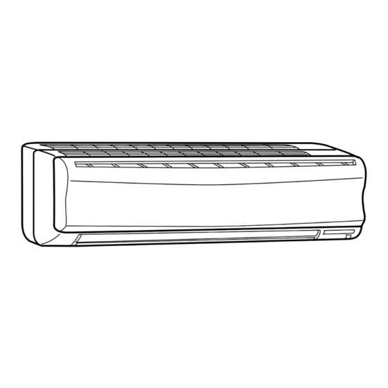
SPLIT-TYPE AIR CONDITIONERS
INDOOR UNIT
SERVICE MANUAL
Wireless type
Model
MSH-GD80VB -
NOTE:
RoHS compliant products have <G> mark on the spec name plate.
• Another type of the electronic control P.C.
board (TYPE 2) has been added to the
original one (TYPE 1). They are both com-
patible with MSH-GD80VB-
Please void OBH513.
E1
Outdoor unit service manual
MUH-GD•VB Series (OBH514)
CONTENTS
1. TECHNICAL CHANGES ··································· 2
2. PART NAMES AND FUNCTIONS ····················· 2
3. SPECIFICATION ················································ 3
4. NOISE CRITERIA CURVES ······························ 3
5. OUTLINES AND DIMENSIONS ························ 4
6. WIRING DIAGRAM ············································ 5
7. REFRIGERANT SYSTEM DIAGRAM ··············· 5
8. SERVICE FUNCTIONS ····································· 6
9. MICROPROCESSOR CONTROL ····················· 8
10. TROUBLESHOOTING ····································· 15
11. DISASSEMBLY INSTRUCTIONS ···················· 24
PARTS CATALOG (OBB513)
.
E1
No. OBH513
REVISED EDITION-A
Advertisement
Table of Contents
Troubleshooting

Related Manuals for Mitsubishi Electric MSH-GD80VB-E1


Summary of Contents for Mitsubishi Electric MSH-GD80VB-E1
-
Page 1: Table Of Contents
Revision A: • Another type of the electronic control P.C. board (TYPE 2) has been added to the original one (TYPE 1). They are both com- SPLIT-TYPE AIR CONDITIONERS patible with MSH-GD80VB- Please void OBH513. INDOOR UNIT No. OBH513 SERVICE MANUAL REVISED EDITION-A Wireless type Model... -
Page 2: Technical Changes
Use the specifi ed refrigerant only Never use any refrigerant other than that specified. Doing so may cause a burst, an explosion, or fire when the unit is being used, serviced, or disposed of. Correct refrigerant is specified in the manuals and on the spec labels provided with our products. We will not be held responsible for mechanical failure, system malfunction, unit breakdown or accidents caused by failure to follow the instructions. -
Page 3: Specification
SPECIFICATION Indoor model MSH-GD80VB Cooling Heating Function Single phase Power supply 230 V, 50 Hz Breaker capacity Running current 0.34 Power input Power factor RC4V40-AA Model Fan motor current 0.34 Dimensions W H D 1,100 325 258 Weight Air direction 954/822/684 954/834/726 Air flow (High/Med./Low) -
Page 4: Outlines And Dimensions
OUTLINES AND DIMENSIONS MSH-GD80VB Unit: mm Installation plate Indoor unit 1068 414.5 414.5 Wall hole 1100 Air in Installation plate Liquid line 9.52- 0.5 m Gas line 12-0.43 m Insulation 50 O.D 32 I.D Drain hose (Connected part O.D) Air out Insulation Power supply cord Lead to right 2.0 m... -
Page 5: Wiring Diagram
WIRING DIAGRAM MSH-GD80VB REFRIGERANT SYSTEM DIAGRAM MSH-GD80VB Unit:mm Refrigerant pipe 15.88 (with heat insulator) Indoor coil Indoor thermistor heat RT12 (main) exchanger Flared connection Indoor coil thermistor RT13 (sub) Room temperature thermistor RT11 Strainer Flared connection Refrigerant flow in cooling Refrigerant flow in heating Refrigerant pipe 9.52... -
Page 6: Service Functions
SERVICE FUNCTIONS MSH-GD80VB 8-1. TIMER SHORT MODE For service, set time can be shortened by short circuit of JPG and JPS on the electronic control P.C. board. (Refer to 10-6.) The time will be shortened as follows. Set time: 1 minute 1-second Set time: 3 minute 3-second (It takes 3 minutes for the compressor to start operation. - Page 7 8-3. AUTO RESTART FUNCTION When the indoor unit is controlled with the remote controller, the operation mode, set temperature, and the fan speed are memorized by the indoor electronic control P.C. board. “AUTO RESTART FUNCTION” automatically starts operation in the same mode just before the shutoff of the main power.
-
Page 8: Microprocessor Control
MICROPROCESSOR CONTROL MSH-GD80VB WIRELESS REMOTE CONTROLLER Signal transmitting section Operation display section OPERATE/STOP (ON/OFF) button ON/OFF WARM COOL TEMPERATURE buttons CLOCK ON/OFF WARM COOL VANE button FAN SPEED CONTROL button (Horizontal vane button) STOP I FEEL COOL OFF-TIMER button VANE START HEAT ON-TIMER button... - Page 9 9-1. COOL ( ) OPERATION 1. Coil frost prevention When the temperature of indoor heat exchanger becomes too low, the coil frost prevention mode works. The indoor fan operates at the set speed and the compressor stops. This mode continues until the temperature of indoor heat exchanger rises.
- Page 10 OBH513A...
- Page 11 9-5. AUTO VANE OPERATION To confirm the standard position, the vane moves until it touches the vane stopper. Then the vane is set to the desired angle. in the following case: The horizontal vane position is set to Upward. OBH513A...
- Page 12 When ECONO COOL button is pressed in COOL mode, set temperature is automatically set 2 C higher. Also the horizontal vane swings in various cycle. SWING operation makes you feel cooler than set temperature. So, even though the set temperature is higher, the air conditioner can keep comfort.
- Page 13 9-6. TIMER OPERATION OBH513A...
- Page 14 9-7. EMERGENCY/TEST OPERATION The indoor fan runs at High speed and the temperature control does not work. the test run or the 9-8. 3-MINUTE TIME DELAY OPERATION When the system turns OFF, compressor will not restart for 3 minutes as 3-minute time delay function operates to protect compressor form overload.
-
Page 15: Troubleshooting
TROUBLESHOOTING MSH-GD80VB 10-1. CAUTIONS ON TROUBLESHOOTING 1. Before troubleshooting, check the following: (1) Check the power supply voltage. (2) Check the indoor/outdoor connecting wire for mis-wiring. 2. Take care the following during servicing. (1) Before servicing the air conditioner, be sure to turn OFF the main unit first with the remote controller, and then after confirming the horizontal vane is closed, turn OFF the breaker and / or disconnect the power plug. - Page 16 10-2. INSTRUCTION OF TROUBLESHOOTING Start Indoor unit Indoor unit Indoor unit operates. OPERATION INDICATOR operates. does not receive Outdoor unit lamp on the indoor unit is Outdoor unit the signal from does not operate flashing ON and OFF. does not remote controller.
- Page 17 10-3. TROUBLESHOOTING CHECK TABLE • Before taking measures, make sure that the symptom reappears for accurate troubleshooting. When the indoor unit has started operation and the following detection method has detected an abnormality (the first detection after the power ON), the indoor electronic control P.C. board turns OFF the indoor fan motor with the OPERATION INDICATOR lamp flashing.
- Page 18 10-4. TROUBLE CRITERION OF MAIN PARTS MSH-GD80VB Part name Check method and criterion Figure Measure the resistance with a tester. Room temperature (Part temperature 10°C ~ 30°C) thermistor (RT11) Indoor coil thermistor Refer to 10-6."Test point diagram and voltage", (RT12 (main), RT13 (sub)) "Indoor electronic control P.C.
-
Page 19: Troubleshooting Flow
10-5. TROUBLESHOOTING FLOW When OPERATION INDICATOR lamp flashes 3-time. Indoor fan motor does not operate. Check of indoor fan motor Turn OFF the power supply. Check connector CN211 visually. Is soldered point of the connector Are lead wires connected? Resolder it. correctly soldered? Reconnect the lead wires. -
Page 20: Check Of Indoor Electronic Control P.c. Board
The unit does not operate with the remote controller. Also, the OPERATION INDICATOR lamp does not light up by pressing the EMERGENCY OPERATION switch. Check of indoor electronic control P.C. board Check the both “parts side” and “pattern Varistor (NR11) side”... -
Page 21: How To Check Mis-Wiring
When OPERATION INDICATOR lamp flashes ON and OFF in every 0.5-second. Outdoor unit does not operate. How to check mis-wiring Short circuit of JPG and JPS on the indoor electronic control P.C. board enables self -check to be displayed in 3 seconds. Start •... - Page 22 10-6. TEST POINT DIAGRAM AND VOLTAGE MSH-GD80VB NOTE: There are two types of electronic control P.C. boards (TYPE 1/TYPE 2). They are both compatible Indoor electronic control P.C. board with MSH-GD80VB TYPE 1 Fan motor power supply (CN211) Power supply input 230 V AC 5 V DC Room temperature...
- Page 23 MSH-GD80VB Indoor electronic control P.C. board TYPE 2 Fan motor power supply (CN211) Power supply input 230 V AC Fuse (F11) T3.15AL250V 5 VDC R132 Room temperature thermistor (RT11) Indoor coil thermistor (RT12 (main)) Indoor coil thermistor (RT13 (sub)) 12 VDC CN121 Vane motor power supply...
-
Page 24: Disassembly Instructions
DISASSEMBLY INSTRUCTIONS <"Terminal with locking mechanism" Detaching points> The terminal which has the locking mechanism can be detached as shown below. There are two types ( Refer to (1) and (2)) of the terminal with locking mechanism. The terminal without locking mechanism can be detached by pulling it out. Check the shape of the terminal before detaching. - Page 25 OPERATING PROCEDURE PHOTOS Photo 4 4. Removing the vane motor (1) Remove the panel and the corner box. (Refer to 1.) Vane motors Screws (2) Remove the electrical cover. (Refer to 2.) of the (3) Remove the lead wire of vane motor. (Refer to 3.) vane (4) Remove the R.L.
- Page 26 HEAD OFFICE: TOKYO BLDG., 2-7-3, MARUNOUCHI, CHIYODA-KU, TOKYO 100-8310, JAPAN Copyright 2008 MITSUBISHI ELECTRIC ENGINEERING CO.,LTD Distributed in Aug. 2011. No.OB REVISED EDITION-A New publication, effective Aug. 2011 Distributed in Apr. 2008. No.OBH513 6 Specifications subject to change without notice.
Need help?
Do you have a question about the MSH-GD80VB-E1 and is the answer not in the manual?
Questions and answers