Sign In
Upload
Download
Table of Contents
Contents
Add to my manuals
Delete from my manuals
Share
URL of this page:
HTML Link:
Bookmark this page
Add
Manual will be automatically added to "My Manuals"
Print this page
×
Bookmark added
×
Added to my manuals
Manuals
Brands
Samsung Manuals
Microwave Oven
CK95
Service manual
Samsung CK95 Service Manual
Samsung ck95/ ck96t/ ck97b/ ck98f microwave oven
Hide thumbs
1
2
3
4
5
6
7
8
9
10
11
12
13
14
15
16
17
18
19
20
21
22
23
24
25
page
of
25
Go
/
25
Contents
Table of Contents
Troubleshooting
Bookmarks
Table of Contents
Table of Contents
Precaution
Table of Specifications
Specifications
Control Panel
Features & External Views
Operating Instructions
Disassembly and Reassembly
Replacement of Door Assembly
Replacement of Fuse/Drive Motor
Alignment and Adjustments
High Voltage Capacitor
High Voltage Diode
Procedure for Measurement of Microwave Energy Leakage
Troubleshooting
Exploded Views and Parts List
Main Parts List
Door Parts List
Control Parts List
Casing Parts List
Standard Parts List
Schematic Diagrams
Advertisement
Quick Links
1
Table of Contents
2
Specifications
3
Table of Specifications
4
Operating Instructions
5
Control Panel
Download this manual
SERVICE
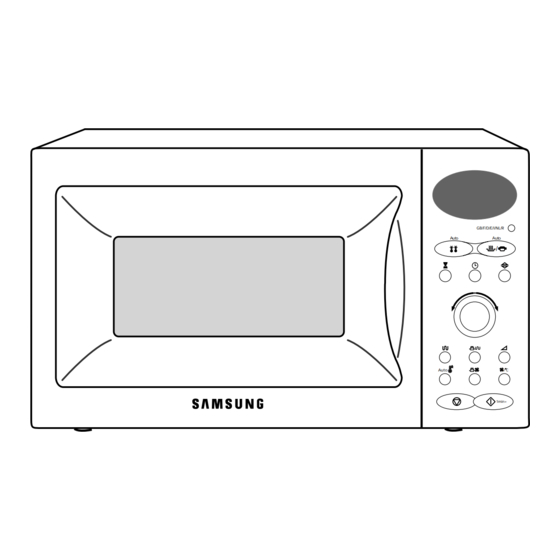
MICROWAVE OVEN
MICROWAVE OVEN
CK95 / CK96T / CK97B / CK98F
1. Precaution
2. Specifications
3. Operating Instructions
4. Disassembly and Reassembly
5. Alignment and Adjustments
GB/F/D/E/I/NL/R
u
/
6. Troubleshooting
Auto
/ C
1min+
7. Exploded Views and Parts List
8. PCB Diagrams
9. Schematic Diagrams
Manual
CONTENTS
Previous
Page
Next
Page
1
2
3
4
5
Advertisement
Table of Contents
Need help?
Do you have a question about the CK95 and is the answer not in the manual?
Ask a question
Questions and answers
Related Manuals for Samsung CK95
Microwave Oven Samsung CK137B Owner's Instructions And Cooking Manual
(36 pages)
Microwave Oven SAMSUNG CK135 Owner's Instructions And Cooking Manual
(48 pages)
Microwave Oven Samsung CK135 Service Manual
(28 pages)
Microwave Oven Samsung CK135M Service Manual
(26 pages)
Microwave Oven Samsung CK99FS Owner's Instructions Manual
(34 pages)
Microwave Oven Samsung CK98F Service Manual
Samsung ck95/ ck96t/ ck97b/ ck98f microwave oven (25 pages)
Microwave Oven Samsung CK95R Service Manual
(26 pages)
Microwave Oven Samsung C100 Owner's Instructions And Cooking Manual
(36 pages)
Microwave Oven Samsung C139ST Owner's Instructions Manual
(84 pages)
Microwave Oven Samsung C109ST Owner's Instructions And Cooking Manual
(36 pages)
Microwave Oven Samsung CE1070 Owner's Instructions And Cooking Manual
(36 pages)
Microwave Oven Samsung CE107MTST Owner's Instructions And Cooking Manual
(32 pages)
Microwave Oven Samsung C106FL Owner's Instructions Manual
(36 pages)
Microwave Oven Samsung C109STFC Owner's Instructions Manual
(36 pages)
Microwave Oven Samsung CE281DN Owner's Instructions Manual
(24 pages)
Microwave Oven Samsung CE2933N Owner's Instructions Manual
(60 pages)
This manual is also suitable for:
Ck96t
Ck97b
Ck98f
Table of Contents
Save PDF
Print
Rename the bookmark
Delete bookmark?
Delete from my manuals?
Login
Sign In
OR
Sign in with Facebook
Sign in with Google
Upload manual
Upload from disk
Upload from URL


Need help?
Do you have a question about the CK95 and is the answer not in the manual?
Questions and answers