Advertisement
Available languages
Available languages
Quick Links
BTF Series Thermostat
Installation Instructions
BTF
BTF TP
TOOLS REQUIRED
Phillips Screwdriver
Wire Connectors
•
•
IMPORTANT INSTRUCTIONS
W RNING
Turn the electrical power off at the electrical panel board (circuit breaker or fuse box) and lock or tag
the panel board door to prevent someone from turning on power while you are working on the heater.
Failure to do so could result in serious electrical shock, burns, or possible death.
If you are uncomfortable working with electrical appliances, unable to follow these
guidelines, or do not have the necessary equipment; consult a licensed electrician.
SAVE THESE INSTRUCTIONS
www.cadetco.com
Tel: 360-693-2505
INSTALLATION INSTRUCTIONS
PART 2 - STEP 5 CONTINUED)
Model BTF2 – 240/208 Volt Application
A. Connect the black thermostat wires to the
B. Connect the hot supply wires to the red
loose heater wires.
thermostat wires.
PROCEED TO PART 3
Model BTF2 – 120 Volt Application
A. Connect the red thermostat
B. Connect the neutral supply
wire labeled L2 to the black
wire to one of the heater wires.
thermostat wire labeled OFF
as shown.
BTF WIRING INSTRUCTIONS CONCLUSION - PART 3
STEP 6
STEP 7
Carefully tuck all wires
Turn the power back on at the
into wiring compartment
circuit breaker or fuse box.
and attach the thermostat
to the baseboard heater.
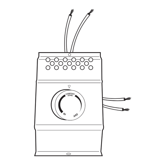
The BTF series heater mount
thermostat for Cadet electric
baseboards can be used to
control a baseboard heater
at the unit. Designed to replace
the detachable baseboard end
plate, the BTF easily installs onto
either end of a Cadet F-series
BTF2
baseboard heater.
The BTF line voltage thermostat
is capable of switching up to
17 amps, of a resistive load,
at 120, 208 or 240 VAC. Setpoint
temperature range: 45º - 80ºF.
NEW Temperature Set Position
BTF2TP
Straight Screwdriver
•
CONTROLS
Turn knob counter-clockwise for cooler room
temperature. Turn knob clockwise for warmer
room temperature.
P.O. Box 1675
Vancouver, WA
98668-1675
C. Connect the supply hot
D. Connect the remaining
wire to the remaining red
black thermostat wire to
thermostat wire.
the remaining heater wire.
PROCEED TO PART 3
STEP 8
STEP 8B - Tamper
Turn the thermostat knob fully
Proof Models
clockwise. When the room
Remove plastic plug and adjust
reaches comfort level, turn
the thermostat shaft to desired
the knob counterclockwise
setting using a screwdriver.
until a slight click is heard.
Replace the plastic plug. The
The heater will now cycle
heater will now cycle around
around this preset temperature.
this preset temperature.
INSTALLATION INSTRUCTIONS
BTF WIRING INSTRUCTIONS - PART 1
STEP 1
STEP 2
Turn the electrical power off at
Remove the junction box cover
the circuit breaker or fuse box.
at the end of the baseboard
you wish to wire.
REFER TO THE INSTRUCTIONS BELOW TH T CORRESPOND TO YOUR THERMOST T
Model BTF1 – 240/208 Volt Application
A. Connect a hot supply wire to the red
B. Connect the black thermostat wire to one
thermostat wire.
of the heater wires.
Model BTF1 - 120 Volt Application
A. Connect the hot supply wire to the red
B. Connect the black thermostat wire to one
thermostat wire.
of the heater wires.
INSTALLATION INSTRUCTIONS
MULTIPLE HEATER WIRING - OPTIONAL
More than one baseboard heater can be wired in parallel on same circuit (be sure to check national and local codes for safety requirements). Addi-
tional wire is required. Important: When wiring multiple heaters to one thermostat, the baseboards must be in the same room.
Maximum amperage rating: 17 amps.
BTF1
1. Disconnect one factory connector on each baseboard.
2. Connect one supply lead to the red thermostat wire.
3. Connect black thermostat wire to one wire on each heater.
4. Connect remaining wire from each heater to the remaining
supply lead.
5. Connect ground wire to both heaters.
IMPORTANT: Wires shown in illustration are for reference only.
All electrical work and materials must comply with the National
Electric Code (NEC) and all state and local codes.
BTF2
1. Disconnect one factory connector on each baseboard.
2. Connect one supply wire to each red thermostat wire.
3. Connect one black thermostat wire to one wire from each heater.
4. Connect remaining black thermostat wire to the remaining wire
from each heater.
5. Connect ground to both heaters.
IMPORTANT: Wires shown in illustration are for reference only.
All electrical work and materials must comply with the National
Electric Code (NEC) and all state and local codes.
WARRANTY
WARRANTY
Warranties are non transferable and apply to original consumer only.
Warranty terms are set out below.
LIMITED ONE-YEAR WARRANTY: Cadet will repair or replace any Cadet
product, including thermostats, found to be defective within one year
after the date of purchase.
THESE WARRANTIES DO NOT APPLY:
1. Damage occurs to the product through improper installation or in-
correct supply voltage;
2. Damage occurs to the product through improper maintenance, misuse,
abuse, accident, or alteration;
3. The product is serviced by anyone other than Cadet.
4. If the date of manufacture of the product cannot be determined;
5. If the product is damaged during shipping through no fault of Cadet.
6. CADET'S WARRANTY IS LIMITED TO REPAIR OR REPLACEMENT AS
SET OUT HEREIN. CADET SHALL NOT BE LIABLE FOR DAMAGES
SUCH AS PROPERTY DAMAGE OR FOR CONSEQUENTIAL DAMAGES
AND/OR INCIDENTAL EXPENSES RESULTING FROM BREACH OF
THESE WRITTEN WARRANTIES OR ANY EXPRESS OR IMPLIED WARRANTY.
STEP 3
STEP 4
Connect the supply grounding
Disconnect one factory connector
wire to the green grounding
on the side you have open,
pigtail provided.
leaving two loose heater wires.
PART 2 - STEP 5
C. Connect the remaining hot supply wire
to the remaining heater wire.
PROCEED TO PART 3
C. Connect the neutral supply wire to the
remaining heater wire.
PROCEED TO PART 3
7. IN THE EVENT CADET ELECTS TO REPLACE ANY PART OF YOUR CADET
PRODUCT, THE REPLACEMENT PARTS ARE SUBJECT TO THE SAME
WARRANTIES AS THE PRODUCT. THE INSTALLATION OF REPLACEMENT
PARTS DOES NOT MODIFY OR EXTEND THE UNDERLYING WARRANTIES.
REPLACEMENT OR REPAIR OF ANY CADET PRODUCT OR PART DOES
NOT CREATE ANY NEW WARRANTIES.
8. These warranties give you specific legal rights, and you may also
have other rights which vary from state to state. Cadet neither assumes,
nor authorizes anyone to assume for it, any other obligation or liability
in connection with its products other than as set out herein.
If you believe your Cadet product is defective, please, contact Cadet
Manufacturing Co. at 360-693-2505, during the warranty period, for
instructions on how to have the repair or replacement processed. Warranty
claims made after the warranty period has expired will be denied. Prod-
ucts returned without authorization will be refused.
Parts and Service
Visit http://support.cadetco.com for information on where to obtain
parts and service.
©2009 Cadet Manufacturing Co.
Printed in U.S.A. 08/10 #720107
PPLIC TION.
Advertisement

Related Manuals for Cadet BTF1


Summary of Contents for Cadet BTF1
-
Page 1: Installation Instructions
BTF WIRING INSTRUCTIONS CONCLUSION - PART 3 WARRANTY 7. IN THE EVENT CADET ELECTS TO REPLACE ANY PART OF YOUR CADET Warranties are non transferable and apply to original consumer only. PRODUCT, THE REPLACEMENT PARTS ARE SUBJECT TO THE SAME Warranty terms are set out below. - Page 2 8. Estas garantías le otorgan derechos legales específicos y es posible incorrectos; que usted tenga otros derechos que varíen de un estado a otro. Cadet no asume ni autoriza a nadie que lo haga en su nombre, ninguna otra 2. Daños que sufra el producto por mantenimiento incorrecto, uso obligación o responsabilidad en relación con sus productos que no...