
Summary of Contents for SUZHOU PARSUN POWER MACHINE F2.6BM
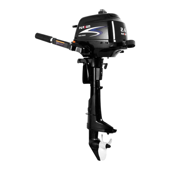
- Page 1 PARSUN OUTBOARD ENGINE SERVICE MANUAL F2.6BM SUZHOU PARSUN POWER MACHINE CO., LTD.
- Page 2 All rights reserved. This manual cannot be reproduced or transmitted in any form or by any means without the written approval of our company. Suzhou Parsun Power Machine Co., Ltd.
-
Page 3: Table Of Contents
INDEX GENERAL INFORMATION· · · · · · · · · · · · · · · · · · · · · · · · · · · · · · · · · · · · · · · · · · 1 IDENTIFICATION·... - Page 4 RECOIL STARTER· · · · · · · · · · · · · · · · · · · · · · · · · · · · · · · · · · · · · · · · · · · · · · · · · 19 NOTICE·...
- Page 5 CRANKCASE· · · · · · · · · · · · · · · · · · · · · · · · · · · · · · · · · · · · · · · · · · · · 43 Disassembling·...
- Page 6 WATER PUMP ASSEMBLY· · · · · · · · · · · · · · · · · · · · · · · · · · · · · · · · · · · 62 Explosive drawing· · · · · · · · · · · · · · · · · · · · · · · · · · · · · · · · · · · · · · · 62 Disassembling and inspection·...
-
Page 7: General Information
GENERAL INFORMATION IDENTIFECATION The outboard motor serial number is marked on the label. The label can be found on the bracket left assembly or on the upper part of the bracket swivel. Record your outboard motor serial number in the spaces provided to assist you in ordering spare parts from your Parsun dealer. To prevent from theft, the serial number label will be destroyed if removed from the outboard motor. - Page 8 items far away. Don’t touch flywheel or other moving parts. When starting and operating, don’t touch ignition coil, spark plug cap or other electric parts. The procedure is as follows: 1. Remove the top cowling. 2. Remove the bolts fixing the fuel tank. 3.
-
Page 9: Safety While Working
8. When the engine is cold , circumvolve the lever of carburetor in order to operate choke system. Return lever to home position after engine starts. Insert the knot of the cable in the notch of flywheel rotor, and wind the cable around flywheel several rounds in clockwise direction. -
Page 10: Disassembly And Assembly
Under normal conditions of use, there should be no hazards from the use of the lubricants mentioned in this manual, but safety is all-important, and by adopting good safety practices, any risk is minimized. A summary of the most important precautions is as follows: 1 To protect the skin, the application of a suitable barrier cream to the hands before working is recommended. - Page 11 Check the engine oil level Check engine oil level from oil level checking hole. 1. High position mark 2. Low position mark Ensure the oil level between the marks of upper and lower. If above upper level, drain engine oil; if below lower mark, add engine oil up to upper level. Check the gear oil level Remove the oil level plug.
-
Page 12: Special Tools And Detection Device
cooling water overflows at the cooling water checking hole. 1. Cooling water checking hole 7. BREAKING-IN RUNNING Initial 1 hour: operate the engine at 2000 r/min or about a half throttle. The second hour: operate the engine at 3000 r/min or about 3/4 throttle. The following 8 hours: operate the engine at full throttle continuously. - Page 13 Valve spring compressor Housing bearing installer Lower casing cover bearing installer Oil seal installer tool Housing oil seal installer Space gage Sleeve bearing with guard board installer tool Lower casing bracket and sleeve bearing without guard board installer tool Lower casing bracket and drive shaft oil seal installer tool DETECTION DEVICE: Digital tachometer Digital universal meter...
-
Page 14: Explosive Drawing And Symbol
EXPLOSIVE DRAWING AND SYMBOL EXPLOSIVE DRAWING M6x40 mm Parts explosive drawing Screw specification and specified torque Oil, fluid sealant or locking substance daubing point Spare parts details SYMBOL 1277 1243 Daub waterproof Daub screw locking Daub screw locking Daub engine oil grease substance 1277 substance 1243... -
Page 15: Specifications
SPECIFICATIONS OUTBOARD ENGINE SPECIFICATIONS Item Description Item Description Overall length 645mm Spark plug BPR7HS Overall width 343mm Exhaust system Under water Lubrication Overall height 1013mm Splash lubrication system Unleaded regular Weight 18.0kg Fuel type gasoline Max output 1.9Kw(2.6hp)@5500r/min Fuel standard PON86 RON91 Full throttle Fuel tank... -
Page 16: Maintenance Information
MAINTENANCE INFORMATION Power Unit Item Description Item Description Valve Intake 0.08~0.12mm 0.1mm Warp limit clearance Exhaust 0.08~0.12mm (cold) 54.00~54.015mm Bore Intake 1.84~2.26mm Face width 54.1mm Wear limit Exhaust 1.84~2.26mm 0.08mm 0.6~0.8mm Taper limit Intake Seat width Out of round limit 0.05mm Exhaust 0.6~0.8mm... -
Page 17: Ignition System
Cont’d Item Description Item Description Valve opening 58~62ºC Intake/Exhaust height 26.139~26.239mm temperature Full-open 70ºC temperature Round diameter 21.950~22.050mm Valve lift Journal diameter 14.966~14.984mm Camshaft round limit 0.03mm Ignition system Item Description Item Description BTDC30º 0.6~0.7mm Ignition timing Spark plug gap T.C.I system output Ignitor 130V... -
Page 18: General Torque
Cont’d Part to be tightened Part name Thread size Quantity Torque 1st tightening 5 Nm Connecting Bolt 9 Nm tightening Oil splash gear unit Bolt 13 Nm Lower unit 1st tightening 3 Nm Bolt mounting 2nd tightening 8 Nm Lower unit 1st tightening housing Bolt... -
Page 19: Periodic Service
PERIODIC SERVICE MAINTENANCE TIME TABLE Initial maintenace General maintenance Items Contents period 10 hours 50 hours 100 hours 200 hours 1 month 3 months 6 months 1 year Anode Inspection/replacement Spark plug Cleaning/adjustment /replacement Grease points Greasing Bolts and nuts Inspection Fuel tank and fuel line Inspection... -
Page 20: Power Unit
POWER UNIT Engine oil level 1. From oil level checking hole, check if engine oil level is between the following marks of the upper and lower. 1. Oil level plug 2. Oil rule 3. High position mark 4. Low position mark 2. -
Page 21: Valve Clearance
3. Fill engine oil into the crankcase through oil filler hole. Engine oil quantity: 0.35L Oil type: API SE, SF, SE-SF, SG-CD SAE 10W30, 10W40 4. Install oil level plug. 5. Check engine oil level. Valve clearance CAUTION: Rotate the flywheel clockwise so that rocker arm is in free position, before adjusting valve clearance (Dead point position on compression stroke). -
Page 22: Control System
CONTROL SYSTEM Throttle grip 1. Turn the throttle grip to fully closed position. 2. Check if the throttle cable is slack and if the throttle lever touches the throttle stop screw. 3. Loosen throttle cable stopper screw, adjust throttle cable position, and tighten throttle cable stop screw. -
Page 23: Lower Unit
LOWER UNIT Gear oil Check gear oil level: Remove the oil level plug. If the gear oil overflows at the oil level checking hole, the oil volume added is correct; otherwise please add gear oil. 1. Oil level plug 1.Oil level plug Changing gear oil 1. -
Page 24: General Inspection
Connecting the leakage tester to the oil level checking hole to check the lower unit leakage. If the pressure drops (pressure: 1kg/cm³), inspect the oil seal and components. GENERAL INSPECTION Anode Inspect lower unit anode and engine anode (on the thermostat cover). Clean the greasy dirt and scales. -
Page 25: Recoil Starter
Cooling water passage inlet 2. Place the outboard engine in the water and ensure the water level is above the anti-vortex plate, then start the engine. 3. Check if water overflows at the cooling water checking hole. If there is no flow or intermittent flow, check the cooling water passage. -
Page 26: Explosive Drawing
EXPLOSIVE DRAWING... -
Page 28: Disassembling
DISASSEMBLING 1. Open the top cowling 2. Remove bolts fixing the fuel tank. 3. Remove the fuel tank and take down three bolts. 4. Lift the starter and remove choke cable from carburetor. 5. Remove the starter. STARTER ROPE REPLACEMENT 1. -
Page 29: Disassembling And Inspection
2. Pull the starter rope completely. 3. Remove the starter handle cover from the starter handle, and remove the starter rope. Untie the knot at the end of the starter rope. 4. Pull out the starter rope completely. 5. Insert the new starter rope into the starter assembly, and fix the rope onto the sheave drum and starter handle. -
Page 30: Assembling
ASSEMBLING Reverse the steps of disassembling. INSTALLATION 1. Put starter onto the power unit. 2. Screw the hexagon bolt, and tighten it according to the specified torque. Specified torque: 8 Nm IGNITION SYSTEM NOTICE When checking and repairing the ignition system, keep your hand, clothes, hair or personal belongings away from the rotating flywheel. -
Page 31: Wiring Diagram
44Nm M6x25 mm M6x12 mm WIRING DIAGRAM... -
Page 32: Spark Plug Ignition
Flywheel Ignition coil Engine stop switch Grounding Spark plug Wire beam color: W White B Black SPARK PLUG IGNITION Remove spark plug cap from spark plug. . Connect the ignition tester to the spark plug cap. Start the engine, and observe the sparks through the discharge window of the tester. WARNING Do not touch any joint part of the lead wire of the tester. -
Page 33: Spark Plug Cap
SPARK PLUG CAP Remove the spark plug. Check if the spark plug cap is broken. Replace if necessary. 2. Install the spark plug cap Turn it clockwise until it is tight. FLYWHEEL MAINTENANCE 1. Use flywheel holder to remove the nut and starter pulley; use flywheel puller to remove flywheel. -
Page 34: Fuel System
FUEL SYSTEM NOTICE Gasoline is inflammable and highly volatile liquid. Its leakage can cause fire and explosion. Don’t start the engine before all joints of the fuel system are connected or installed. When completing all maintenance steps, force short-time pressure to the fuel system to check for leakage. -
Page 35: Explosive Drawing
EXPLOSIVE DRAWING... - Page 37 M6x75 mm...
-
Page 38: Fuel Tank Removal And Inspection
FUEL TANK REMOVAL AND INSPECTION Open the top cowling. Remove two bolts fixing the fuel tank. Pull the fuel tank out. Remove the fuel pipe from fuel tank. Inspect if the fuel tank and fuel tank cover for crack, leakage or damage. Replace if necessary. -
Page 39: Power Unit
POWER UNIT NOTICE To avoid accidental start of outboard engine during maintenance, please take enough safety measures to cut the ignition system. For instance, remove engine stop lanyard from engine stop switch assembly, and remove spark plug cap from spark plug. EXPLOSIVE DRAWING... - Page 40 M6x20 mm 25Nm M8x60 mm 1st 14Nm 2nd 30Nm M6x16 mm 1st 5Nm 2nd 12Nm...
- Page 41 M6x20 mm 25Nm M8x60 mm 1st 14Nm 2nd 30Nm M6x16 mm 1st 5Nm 2nd 12Nm...
- Page 42 10Nm 1277 1277...
- Page 43 M6x12mm 13Nm M8x14mm 20Nm M8x20mm 18Nm M6x45mm 1st 5Nm 2nd 11Nm 1277...
- Page 44 M6x12mm 13Nm M8x14mm 20Nm M8x20mm 18Nm M6x45mm 1st 5Nm 2nd 11Nm 1277...
- Page 45 M6x29mm 1st 5Nm 2nd 9Nm...
-
Page 46: Special Tools
SPECIAL TOOLS Piston slider Bearing puller Valve spring compressor Housing bearing installer Oil seal installer tool Housing oil seal installer Space gauge DISASSEMBLING POWER UNIT FROM OUTBOARD ENGINE Open the top cowling. Remove fuel tank; remove starter. Remove flywheel cover and throttle cable . Remove air filter and carburetor. -
Page 47: Push Rod
Remove the rocker arm pivot, rocker arm, rocker arm shaft and push rod plate. Use the valve spring compressor to remove intake door and exhaust door. Push rod Inspect valve push rod runout. Replace if exceeding the specified value. Valve push rod runout limit: 0.5mm Valve and valve pipe 1. -
Page 48: Valve Rocker Arm
Valve rocker arm Check the rocker arm for crack, perforation or damage. Replace if necessary. Valve pipe replacement 1. Knock out the valve pipe from the direction of combustion room. 2. Knock in the new valve pipe from the direction of the top of cylinder cover. NOTE: Coat the oil on the surface of pipe before installation. -
Page 49: Thermostat
4. If the valve seal surface is too narrow and on the bottom edge of valve surface, use 60 cutter to adjust the bottom edge of the seat, and use 45 cutter to adjust the valve seat width if necessary. Coat evenly a thin layer of lapping compound onto valve seat, and lap the valve by lapping tool. -
Page 50: Piston
Remove crankcase and crankcase gasket. Remove oil splasher gear assembly. Remove oil seal shell bolts, and remove oil seal shell and oil seal. Piston Measure piston outside diameter at the specified measuring point. If out of specification, replace. Piston diameter: 53.950 53.965mm Measuring point a : 0mm Cylinder bore... -
Page 51: Crankshaft
Inspect camshaft decompressor, gear, and weight. If gear is worn/damaged/cracked, replace. If weight is unsmoothly moving, replace. 2. Measure camshaft lobe diameter a and height b . If out of specification, replace it. a Camshaft: 21.950 22.050mm b Camshaft: 26.136 26.239mm Measure camshaft diameter. -
Page 52: Valve Lifter
Valve lifter 1. Inspect valve lifter for wear or damage. Replace if necessary. Measure valve lifter outside diameter. If out of specification, replace the valve lifter. Valve lifter outside diameter: 7.9650mm Oil splash gear Inspect oil splash gear unit, if slow-moving/wear/damage/crack, replace. Crankshaft bearing Inspect bearing, if pitting/rumbling, replace. -
Page 53: Piston Installation
Piston installation Use piston slider to install piston, and make sure the piston crown “UP” is toward the flywheel side. NOTE: Apply motor oil to the piston and piston ring side when installing. Oil seal housing installation. 1. Install oil seals 10.8x21x7 (2 pieces) by oil seal installer tool. Install oil seals B20 30 7 by oil seal installer tool. -
Page 54: Crankcase Cover Installation
Apply motor oil to moving parts before installing. Crankcase cover installation 1. Install oil seal housing. 2. Install oil splasher gear assembly. 3. Install crankcase cover, and tighten the bolts twice as shown. Tightening torque: 1st 5 Nm 2nd 11 Nm NOTE: Apply motor oil to moving parts before installing. -
Page 55: Disassembling And Inspection
Disassembling and inspection Remove intake silencer bolt. Remove intake silencer and intake silencer damper.. Inspect if top cowling, intake silencer and intake silencer damper are cracked or damaged. Replace if necessary. -
Page 56: Bottom Cowling
BOTTOM COWLING Explosive drawing Disassembling and inspection Remove bottom-cowling seal. Remove top cowling locking hook. Remove circular rubber plug and quadrate rubber plug. -
Page 57: Steering Handle
Inspect if bottom cowling is cracked or damaged. Replace if necessary. Inspect if top cowling locking hook is cracked or damaged. Replace if necessary. STEERING HANDLE Explosive drawing 1243 M8x25mm 18Nm... -
Page 58: Disassembling And Inspection
1243 M8x25mm 18Nm Disassembling and inspection 1. Remove steering handle cover. 2. Remove handle bush, bush washer and wave washer. 3. Remove steering handle damper assembly. -
Page 59: Bracket
Remove friction adjusting bolt. Remove steering handle. Remove throttle cable. Remove throttle lever stay and throttle lever. Remove engine stop switch. Inspect if steering handle is cracked or damaged. Replace if necessary. Inspect if bush, bush washer and wave washer are cracked or damaged. Replace if necessary. - Page 60 M6x30 mm 12Nm 16 Nm 5 Nm 5 Nm...
- Page 61 M6x30 mm 12Nm 16 Nm 5 Nm 5 Nm...
- Page 62 M6x30 mm 12Nm 16 Nm 5 Nm 5 Nm...
-
Page 63: Disassembling And Inspection
Disassembling and inspection Remove clamp handle and bracket cover. Remove swivel bracket cover. Remove swivel bracket bushing and damper . Remove clamp bracket Remove swivel bracket. Remove title clamp handle and title lock lever. Inspect the the swivel bracket and clamp bracket for damage or crack. Replace if necessary. 8. -
Page 64: Upper Unit
UPPER UNIT Explosive drawing M6x25 mm 5 Nm M6x20mm 10Nm... - Page 65 M6x25 mm 5 Nm M6x20mm 10Nm...
-
Page 66: Disassembling And Inspection
M6x25 mm 5 Nm M6x20mm 10Nm Disassembling and inspection 1. Remove the water tube. Remove gear shift handle assembly. - Page 67 Remove the shift rod and shift rod lever. 4. Remove exhaust cover. 5. Check upper casing for crack or wear. Replace if necessary. 6. Check gear shift handle for wear or damage. Replace if necessary. 7. Check exhaust cover for crack or wear. Replace if necessary.
-
Page 68: Lower Unit
LOWER UNIT WATER PUMP ASSEMBLY Explosive drawing M6x40 mm... -
Page 69: Disassembling And Inspection
Disassembling and inspection Remove water pump fixed plate. Remove water pump housing. emove impeller, inner housing and O ring of water pump inner housing. Remove water pump base. Check water pump housing and out plate for crack, crank or damage. Replace if necessary. Check inner water pump housing and impeller for crack, deform, burn or damage. -
Page 70: Lower Unit
LOWER UNIT Explosive drawing M6x16mm 1277 1277 M6x30 1st 3Nm 2nd 8Nm M6x12mm 1st 3Nm 2nd 8Nm... - Page 71 M6x16mm 1277 1277 M6x30 1st 3Nm 2nd 8Nm M6x12mm 1st 3Nm 2nd 8Nm...
- Page 72 M6x16mm 1277 1277 M6x30 1st 3Nm 2nd 8Nm M6x12mm 1st 3Nm 2nd 8Nm...
-
Page 73: Disassembling And Inspection
Disassembling and inspection 1 Remove cotter pin, nut assy, and spacer. 2 Remove propeller assembly and spacer. 3 Remove the lower casing cover. 4 Remove drive shaft, positive gear assy, and shift plug. 5 Remove shift rod cam assy and drive shaft. 6 Remove sleeve bearing with guard board. -
Page 74: Lower Casing Cover Oil Seal And Bearing Installation
Lower casing cover oil seal and bearing installation Install oil seal. Note: Please use special tool to install oil seal and bearing. Pay attention to the oil seal installation direction and installation depth. Sleeve bearing Inspect sleeve bearing with guard board and sleeve bearing without guard board for wear, crack or damage. - Page 75 Lower casing bracket and drive shaft oil seal installer tool...
-
Page 76: Common Troubles And Solutions
COMMON TROUBLES AND SOLUTIONS Trouble type Possible reason Recovery action Starter will not operate Starter components are faulty Repair or replace Fuel tank is empty Fill tank with clean, fresh fuel Fuel is contaminated or stale Air vent screw not loosened Loosen air vent screw Spark plug(s) fouled or of incorrect Inspect spark plug(s). - Page 77 Cont’d Trouble type Possible reason Recovery action Check for pinched or kinked fuel line or Fuel system is obstructed other obstructions in fuel system Fuel is contaminated or stale Fill tank with clean, fresh fuel Spark plug gap is incorrect Inspect and adjust as specified Check wires for wear or breaks.
Need help?
Do you have a question about the F2.6BM and is the answer not in the manual?
Questions and answers