
Subscribe to Our Youtube Channel
Related Manuals for Composite-ARF SPARK


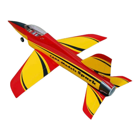
Summary of Contents for Composite-ARF SPARK
-
Page 1: Instruction Manual
Composite-ARF SPARK techsupport@composite-arf.com Instruction Manual Composite-ARF SPARK TAVS Technology version 1.0... -
Page 2: Liability Exclusion And Damages
If you want a full-color version of this manual, you can download it free from our website as an Adobe Acrobat .pdf file and print it (paper size A4). Just go to the ‘Spark’ page on our website, and click on the link named ‘Download Instructions’ above the top photo of the product. -
Page 3: Pre-Flight Checks
This jet aircraft is a high-end product and can create an enormous risk for both pilot and spec- tators, if not handled with care, and used according to the instructions. Make sure that you oper- ate your Spark according to the the laws and regulations governing model flying in the country of use. -
Page 4: Description Of Parts
The fuselage, wing and stabiliser are produced in negative molds, manufactured using vacuum- bagged sandwich construction technology. Due to very careful design, material selection and lamination processes the Spark has incredible strength, yet an extremely lightweight airframe. The composite sandwich parts are extremely strong, but fragile at the same time. Always keep in mind that these contest airplanes are designed for minimum weight and maximum strength in flight. -
Page 5: Tools And Adhesives
This is a very quick and easy plane to build, not requiring special techniques or equipment, but even the building of Composite-ARF aircraft requires some suitable tools. You will probably have all these tools in your workshop anyway, but if not, they are available in all good hobby shops, or hardware stores like "Home Depot"... - Page 6 Our Spark's size is very carefully planned, so that you can fly with the performance of the real big guys, but can stay with just that slightly smaller fan, that slightly smaller battery, that slightly smaller motor - which saves you serious money on the one hand, and converts the power of these just slightly smaller components into breathtaking flight performance.
- Page 7 Accessories This is a list of the things you may need to get your Composite-ARF EDF-powered Spark into the air. Some of them are mandatory, some of them can be chosen by you. What we list here are highly recommended parts, and have been thoroughly tested.
-
Page 8: Building Instructions
Be very careful not to add any uneccessary weight in the nose area (EDF version Spark), other- wise you may need to add lead in the tail to set the Centre of Gravity correctly. - Page 9 Composite-ARF SPARK techsupport@composite-arf.com Rudder Install the rudder servo and linkage first, so you won’t have to remove the thrust tube again later. The Fin is very narrow and it it only possible to fit a servo of up to 15mm (5/8”) thick.
-
Page 10: Edf Installation
Composite-ARF SPARK techsupport@composite-arf.com EDF installation Start the main assembly of the Spark by installing your EDF (Electric Ducted fan) unit, and completing the inlet and exhaust ducting. The inlet ducts have been factory installed for you, and the clear fibreglass ‘Inlet Joiner’ tube connects these to the EDF. - Page 11 Composite-ARF SPARK techsupport@composite-arf.com reinforce with a small bead of medium CA. Do NOT use any activator/kicker or the CA glue and shroud will turn white and ugly, and the heat pro- duced could even deform the shroud. Now take the clear fiberglass inlet joiner and sand the front and back flanges to 10mm wide.
- Page 12 Composite-ARF SPARK techsupport@composite-arf.com 75 EDF unit. The tube should be joined using contact adhesive at the overlap, and also a length of clear tape on both the inside and out- side surfaces of the overlapping joint. Make up the jig used to join the thrust tube using the 2 milled plywood discs included in the wood pack.
- Page 13 Composite-ARF SPARK techsupport@composite-arf.com install the fan unit and slide the front of the tube over the shroud into the final position - so that you can mark and cut the outlet end so that it is flush with the back of the fuselage.
-
Page 14: Horizontal Stabiliser
Composite-ARF SPARK techsupport@composite-arf.com Horizontal Stabiliser The one-piece stab is factory-finished for you. It is secured to the fuselage by a 6mm carbon dowel at the front, that fits into an 8mm carbon tube in the fuselage, and a pair of M4 Allen bolts... - Page 15 Composite-ARF SPARK techsupport@composite-arf.com bly need to be enlarged a little, depending on your servo choice. Do not cut through the car- bon rovings on the top and bottom edges of the balsa spars if you enlarge these servo hatches. Sand the front edge of the forward servo mount...
- Page 16 Composite-ARF SPARK techsupport@composite-arf.com Wing The wing is also 99% factory-completed for you. All wing fixings are completed, phenolic aileron horns are jig-installed, and the elastic-hinged speedbrake is already cut out in the front of the wing centre-section. Strong laminated plywood...
- Page 17 Composite-ARF SPARK techsupport@composite-arf.com don’t hit the spar at 45° throw. If you chose to fit servos without integral wing- mount brackets, you can just add a couple of extra milled liteply pieces to increase the mount height to flush with the top of the servo, and then secure using the small screws thru’...
- Page 18 Composite-ARF SPARK techsupport@composite-arf.com very effective, and is needed on landing as the specially designed wing profile for the Spark has extremely low drag at high loads - and the plane tends to float on and on if you don’t use it.
-
Page 19: Main Landing Gear
(see photo below/right ) Main Landing Gear The Spark was designed to use low-cost, light- weight and reliable retractable landing gear, and the Spring Air 301’s fit this specification perfect- ly. - Page 20 - and therefore the (above) The Spring-Air 301 ‘Firewall’ retract biggest rotation angle before the stabiliser tips set fits the Spark perfectly and is available as touch the runway. For the same reason, only an option directly from Composite-ARF.
- Page 21 Composite-ARF SPARK techsupport@composite-arf.com axles. Retract the legs to check for the exact position that the axles need to be secured to the legs, and then tighten the set screws in the ends of the axles. Remove the legs from the retract units and also the wheels and brake units.
-
Page 22: Cockpit Canopy
Composite-ARF SPARK techsupport@composite-arf.com Cockpit Canopy The fibreglass canopy frame has already been trimmed at the factory, and the fixings completed. The front is secured with a wire through a plastic tube from the nose, the upper back end with a small plywood tongue, and the sides are aligned with 2 small phenolic tabs into slots in the cockpit flange. - Page 23 Composite-ARF SPARK techsupport@composite-arf.com (below) Clear canopy is trapped in place with When the canopy is tacked into the frame, and it epoxy/micro-balloons mixture. Also note the cannot twist any more, you can carefully remove short tube that accepts the nose fixing wire.
- Page 24 Composite-ARF SPARK techsupport@composite-arf.com arm on the right side. File only a very small ‘flat’ for the set screws in the wheel collars (in the trunion block and steering arm) to grip onto, oth- erwise you will weaken the wire leg. Make sure that the plastic bracket slides up and down the steering arm smoothly.
- Page 25 - depend- ing on the ambient temperatures that you will operate your Spark in. Make up the 3 small 6mm thick mounting blocks by gluing short lengths of the 3mm Liteply strip together with thin CA, and sand to shape to fit on the ducts.
- Page 26 Composite-ARF SPARK techsupport@composite-arf.com (below) Rear battery support bulkhead is fac- of Gravity location is almost perfect, only need- ing the small RX battery for final adjustment. If tory-installed. The battery tray has a milled tab that fits in the central slot, arrowed here.
- Page 27 Remember that all the waste energy dissipated by the LiPo batteries, Speed-controller and elec- tric motor that power your Spark is expelled as heat inside the fuselage. It is normally the Speed- controller that has the hardest job, and gets the hottest, and it is very important that you make adequate provision for enough cooling air to enter, and exit, the fuselage - and make sure that it is directed over these 3 critical components, especially the speed-controller.
- Page 28 The amount of air needed to cool the controller will also depend on the ambient temperatures where you will fly your Spark. The inlet cooling air enters thru’ both the nosegear opening, and also from the small slots that you must cut on either side of the canopy frame (see below).
- Page 29 Composite-ARF SPARK techsupport@composite-arf.com Increased Cooling If the speed controller still becomes too warm during normal flying, or you will operate in very warm ambient temperatures, we recommend that you use the following method to increase the cooling flow thru’ the heat sink fins on the speed-controller (see diagram below).
- Page 30 Composite-ARF SPARK techsupport@composite-arf.com parallel to the back of the canopy opening. If you wish you can reinforce the narrow strips between the slots with one carbon roving, as shown. We have included some 160 gram fibre- glass cloth and carbon roving in the hardware.
- Page 31 Composite-ARF SPARK techsupport@composite-arf.com Nose steering servo The nose gear steering servo is normally fitted inverted on the milled plywood mount that you have installed, but if you want to use a single RX channel to control Rudder and Steering, then you must mount the servo the other way up.
- Page 32 Spark, both with (below) The Rx antenna was cut at the wing the motor running and off. Electric models are...
- Page 33 Composite-ARF SPARK techsupport@composite-arf.com (below) The Rx antenna in the wing is in a servo cables), on the outside of the inlet, down to the front of the wing opening. Here we cut the plastic tube in the leading edge. antenna, leaving about 75mm extra before sol- dering on the plug, and this is inserted into the wing thru’...
- Page 34 The Schübeler DS-75 fan unit and the Jeti Spin 99 speed-controller come pre-wired for you, at the correct length for this set-up in the Spark. The gold connectors are already soldered on to the correct length wires for you; the 3 connectors between the speed controller and fan motor are Ø...
-
Page 35: Battery Charging
Make this final connection quickly - or you will get small spark, which is not dangerous - but can cause you some ‘surprise’ the first time it happens! When the system is correctly connected and armed you will get a short musical ‘chime’... - Page 36 We use the Orbit Microlader Pro (available from C-ARF as product #961200) and a pair of Schulze balancers and charge the packs in series as a 10S cell. Quality balancers are available from many sources, including Orbit, Graupner, Schulze, Emcotec etc. Setting Up Your Spark Centre of Gravity: 145 - 150mm...
- Page 37 The airfoil was developed by Robert Vess in the US for scale model race planes. Its minimum drag at high loads made us choose this airfoil for the Spark. Large stab surfaces make the Spark an uncritical flyer. The wings’ geometry with the low drag tips accounts for the Spark's agility and performance.
- Page 38 Composite-ARF SPARK techsupport@composite-arf.com (left) A nice fly-by with a pre- production Spark, owned and flown by one of our UK Reps, Dave Wilshere of Motors and Rotors. (above) A couple of views of the 1st prototype, taken just before the extremely suc-...
-
Page 39: Hardware Pack
Composite-ARF SPARK techsupport@composite-arf.com Appendix Kit Contents: SPARK Kit Quantity Description Fuselage Wing Fibreglass sheet, painted (servo cover set) Stabiliser Linkage cover, painted (for Rudder) Canopy frame (fiberglass) Clear canopy Thrust Tubes (pre-cut mylar sheet) Inlet Joiner (fibreglass) Set of Protection bags (wings, stabs and rudder) 5 pieces... -
Page 40: Available Accessories
Schübeler DS-75 EDF unit & speed-controller set Set two HDHE Lipos 5200 mAH Powerbox Digi-Switch Orbit Microlader Pro Lipo charger Spring-Air 301 Firewall set Behotec ‘slim’ Spark wheels, brakes, axles & valve set Turbine upgrade set (check website for availability) - Page 41 Composite-ARF SPARK techsupport@composite-arf.com Standard Wood parts included in the kit Fuselage hardware pack Wing hardware pack Stabilisers hardware pack...
-
Page 42: Optional Items
Composite-ARF SPARK techsupport@composite-arf.com OPTIONAL ITEMS EDF set (item #864003) Schübeler DS-75 with motor installed, & Jeti Spin 99 Speed-Controller, all wired. Flight battery set (item #865001) Landing gear set (item #740500) two 5200mAH 5S Lipo packs, wired. Spring Air 301 ‘Firewall mount’ set AVAILABLE LATER.
Need help?
Do you have a question about the SPARK and is the answer not in the manual?
Questions and answers