Table of Contents
Advertisement
Advertisement
Table of Contents

Summary of Contents for JETStream JMC-1105
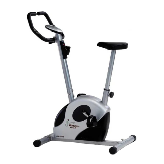
- Page 1 HOME MAGNETIC CYCLE ASSEMBLY INSTRUCTION JMC-1105 Owner's manual...
- Page 2 JMC-1105 MAGNETIC CYCLE ASSEMBLY INSTRUCTION THIS OWNER'S MANUAL CONTAINS ASSEMBLY, OPERATION, MAINTENANCE AND SAFETY INFORMATION. IN THE INTEREST OF SAFETY, PLEASE MAKE CERTAIN THAT YOU READ AND UNDERSTAND ALL THE INFORMATION BELOW. Important safety precautions 1. Read the owner's manual and all accompanying literature and follow it carefully before using your machine.
- Page 3 Warning : Before commencing with any exercise program, please consult your family physician. If at any time during exercise you feel faint, dizzy or experience pain, stop and consult your family physician. In the event any of the above mentioned warnings are breached by the consumer, the manufacturer may use same as a defense to any claim for injuries, damage or loss.
- Page 4 STEP 1. Attach both stabilizers (02,03) to main frame (01). Fix with bolts (04), arc washers (05) & domed nuts (06). STEP 2. IMPORTANT : READ ALL STEPS BEFORE ATTACHING PEDALS. a. Attach pedal (22R & 22L) to pedal cranks. (pedal marked "L" and "R" indicates left and right side of bike, make sure not to mix up) b.
- Page 5 STEP 3. Attach saddle (08) to seat post (09), fastened with washers (07) and nuts (11). Then attach seat post (09) to main frame (01). Adjust saddle (08) to desired height and tighten with adjustment knob (18). STEP 4. Connect computer cable low (21) & computer cable up (19), tension control cable up (13) & tension control cable low (14), then attach handlebar post (12) to main frame (01), fix with washers (05) and bolts (28).
- Page 6 Insert hand pulse wire (10A) into side hole on handlebar post (12) and through the hole on monitor plate. Connect computer cable up (19) and hand pulse wire (10A) onto monitor (20), then attach monitor (20) to the plate on handlebar post (12) with screws (20A). NOW YOUR JMC-1105 HAS BEEN WELL ASSEMBLED. - 5 -...
- Page 7 EXPLODED VIEW 10A 25 31L 30L - 6 -...
-
Page 8: Parts List
PARTS LIST DESCRIPTION Q'TY Main frame Front stand tube Rear stand tube Bolt M8 x 60 Arc washer 8 x 20 Domed nut M8 Washer 8 x 17 x 1.2 Saddle Seat post Hand pulse sensor Hand pulse wire Nut M8 Handlebar post Tension control cable up Tension control cable low...

Need help?
Do you have a question about the JMC-1105 and is the answer not in the manual?
Questions and answers