
Summary of Contents for CHUNLAN FRD23
-
Page 1: Service Manual
Structure & Features Air duct Type Air Conditioner Service Manual JIANGSU CHUNLAN REFRIGERATING EQUIPMENT Co., Ltd. AUGUST 2004... -
Page 2: Table Of Contents
Structure & Features Contents Chapter I Structure & features ................... 1 Chapter II Exploded views & dismantling sequence of parts ..........4 Chapter III Main technical parameters ................34 Chapter IV Performance curve ................... 40 Chapter V Circuit diagrams....................41 Chapter VI List of main parts and wear parts.............. -
Page 3: Chapter I Structure & Features
Air exhaust PTC aux. electric Wire controller heating Return air port Fresh air port Remote controller Water outlet FRD23-B, FRD35-B & FRD50-B indoor unit outline Electric Air exhaust Mounting hole Wire controller Remote Evaporator controller FR(D)71-B & FR(D)100-B indoor unit outline... - Page 4 Structure & Features 2. Indoor unit of medium static pressure series air duct type air conditioner Electric box Wire controller Remote controller Air exhaust Lifting lug mounting position FR95-C & FR125-C/S indoor unit outline 3. Indoor unit of high static pressure series air duct type air conditioner Mounting strip Electric Wire controller...
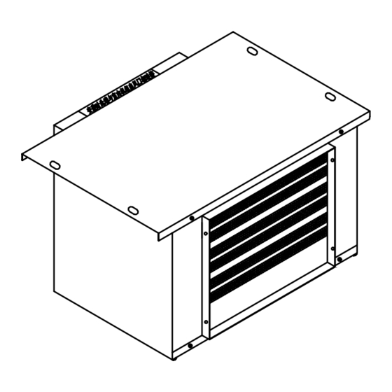
- Page 5 Structure & Features Air intake FRD95, FRD125/S, FRD180/S & FRD20/S auxiliary electric heating box outline III Outdoor units FRD23-B, FRD35-B, FRD50-B outdoor unit FRD71-B, FR71-B outdoor unit Air intake Air exhaust FR(D)95, FR(D)125/S, FR95-C, FR125-C/S, FR(D)100-B outdoor unit outline Air exhaust...
-
Page 6: Chapter Ii Exploded Views & Dismantling Sequence Of Parts
Exploded view & dismantling sequence of parts Chapter II Exploded views & dismantling sequence of parts I. Exploded view & dismantling sequence of indoor unit of FRD23-B, FRD35-B and FRD50-B 1. Exploded view of FRD23-B, FRD35-B and FRD50-B indoor unit Exploded view of indoor unit of FRD23-B, FRD35-B &... - Page 7 Exploded view & dismantling sequence of parts 2. Exploded view schedule for FRD23-B, FRD35-B and FRD50-B in door unit Description Remark Air exhaust strip Water tray assembly Water accumulation plate Right side plate assembly Heat exchanger assembly PTC electric heater...
-
Page 8: Table Of Contents
(4) Remove connecting plug from control board in electric box (5) Remove motor 10 and capacitor. Note: Return air box of FRD23-B, FRD35-B or FRD50-B indoor unit is optional. There are two modes of air return (lower air return and rear air return) and two modes of water discharge (left and right). - Page 9 Exploded view & dismantling sequence of parts II. Exploded view and dismantling sequence for outdoor unit of FRD23-B, FRD35-B & FRD50-B 1. Exploded view of outdoor unit of FRD23-B, FRD35-B and FRD50-B Exploded view of outdoor unit of FRD23-B, FRD35-B and FRD50-B...
- Page 10 Exploded view & dismantling sequence of parts 2. Exploded view schedule of outdoor unit of FRD23-B, FRD35-B and FRD50-B Description Remark Front plate assembly Small shutoff valve Large shutoff valve Compressor Axial flow fan Motor Reversing valve assembly Left rear plate assembly...
-
Page 11: Annex: Dismantling Sequence Of Typical Parts
Exploded view & dismantling sequence of parts 3. Dismantling sequence of outdoor unit of RD23-B, FRD35-B and FRD50-B (1) Remove 11 (2) Remove 8, 9 (3) Remove 14 (4) Remove 1 (5) Remove 10 (6) Remove 5, 6 (7) Remove 16 (8) Remove 2, 3 (9) Remove 15 (10) Remove 7... - Page 12 Exploded view & dismantling sequence of parts III. Exploded view and dismantling sequence of indoor unit of FR(D)71-B and FR(D)100-B 1. Exploded view of indoor unit of FR(D)71-B and FR(D)100-B Indoor unit Exploded view of indoor unit of FR(D)71-B and FR(D)100-B - 10 -...
- Page 13 Exploded view & dismantling sequence of parts 2. Exploded view schedule of indoor unit of FR(D)71-B and FR(D)100-B Description Remark 1 Air intake plate 2 Top plate assembly 3 Left support 4 PTC electric heater Only for FRD71-B & FRD100-B 5 Spiral casing 6 Impeller 7 Left side plate assembly...
-
Page 14: Remove
Exploded view & dismantling sequence of parts 3. Dismantling sequence of indoor unit of FR(D)71-B and FR(D)100-B (1) Remove 18 (2) Remove 17 (3) Remove 4, 3, 15 (4) Remove 2 (5) Remove 1 (6) Remove 5, 6 (7) Remove 12 (8) Remove 14 (9) Remove 13 (10) Remove 8... - Page 15 Exploded view & dismantling sequence of parts IV. Exploded view and dismantling sequence of outdoor unit of FR(D)71-B 1. FR(D)71-B outdoor unit exploded view FR(D)71-B outdoor unit exploded view - 13 -...
- Page 16 Exploded view & dismantling sequence of parts 2. Exploded view schedule for FR(D)71-B outdoor unit Description Remark Front panel assembly Axial flow fan Motor Motor support assembly Condenser Left panel Top cover assembly Air intake grating Baffle plate assembly 10 Right panel assembly 11 Handle 12 Electric assembly 13 Valve support assembly...
- Page 17 Exploded view & dismantling sequence of parts 3. FR(D)71-B outdoor unit dismantling sequence (1) Remove 7 (2) Remove 11, 13 (3) Remove 1 (4) Remove 10 (5) Remove 8, 6 (6) Remove 18 (7) Remove 2, 3 (8) Remove 4 (9) Remove 12 (10) Remove 14, 15 (11) Remove 16...
- Page 18 Exploded view & dismantling sequence of parts V. Exploded view and dismantling sequence of indoor unit of FR95-C, FR125-C/S 1. Exploded view of indoor unit of FR95-C and FR125-C/S - 16 -...
- Page 19 Exploded view & dismantling sequence of parts 2. Exploded view schedule of indoor unit of FR95-C and FR125-C/S Description Remark Cover plate assembly Top plate assembly Lifting hook Electric box assembly Left support plate Small side plate assembly Fixing support assembly Fixing support cover plate assembly Spiral casing assembly 10 Centrifugal impeller...
- Page 20 Exploded view & dismantling sequence of parts 3. Dismantling sequence of indoor unit of FR95-C and FR125-C/S (1) Remove 1 (2) Remove 11, 14 (3) Remove 2 (4) Remove 4, 3 (5) Remove 21 (6) Remove 9, 10 (7) Remove 12, 13 (8) Remove 8 (9) Remove 7 (10) Remove 22...
- Page 21 Exploded view & dismantling sequence of parts VI. Exploded view and dismantling sequence of indoor unit of FR(D)95 and FR(D)125/S 1. Exploded view of indoor unit of FR(D)95 and FR(D)125/S Exploded view of indoor unit of FR(D)95 and FR(D)125/S - 19 -...
- Page 22 Exploded view & dismantling sequence of parts 2. Exploded view schedule of indoor unit of FR(D)95 and FR(D)125/S Description Remark Top plate assembly Strainer 1 Evaporator assembly Strainer 2 Water tray assembly Strainer retaining strip Left side plate assembly Fixing block Left small hole cover plate 10 Square hole cover plate assembly 11 Air intake...
- Page 23 Exploded view & dismantling sequence of parts 3. Dismantling sequence of indoor unit of FR(D)95 and FR(D)125/S (1) Remove 1; (2) Remove 2; (3) Remove 8, 4; (4) Remove 14, 16; (5) Remove 23; (6) Remove 7; (7) Remove 3; (8) Remove 5;...
- Page 24 Exploded view & dismantling sequence of parts VII. Exploded view and dismantling sequence of auxiliary electric heating box of FRD95 and FRD125/S Exploded view of auxiliary electric heating box of FRD95 and FRD125/S Exploded view schedule of auxiliary electric heating box of FRD95 and FRD125/S Description Remark Top plate...
- Page 25 Exploded view & dismantling sequence of parts VIII. Exploded view and dismantling sequence of outdoor unit of FR(D)95, FR(D)125/S, FR(D)100-B, FR95-C and FR125-C/S 1. Exploded view of outdoor unit of FR(D)95, FR(D)125/S, FR(D)100-B, FR95-C & FR125-C/S Exploded view of outdoor unit of FR(D)95, FR(D)100-B, FR(D)125/S, FR95-C, FR125-C/S (example of FR(D)95) - 23 -...
- Page 26 Exploded view & dismantling sequence of parts 2. Exploded view schedule of outdoor unit of FR(D)95, FR(D)125/S, FR(D)100-B, FR95-C & FR125-C/S Description Remark Top cover assembly Air intake mesh assembly Right panel assembly Condenser Capillary assembly T-pipe assembly Valve Dg8 Motor support 10 Flat washer 5 11 Spring washer 5...
- Page 27 Exploded view & dismantling sequence of parts 3. Dismantling sequence of outdoor unit of FR(D)95, FR(D)125/S, FR(D)100-B, FR95-C、& FR125-C/S (1) Remove 1; (2) Remove 2; (3) Remove 3 and 4 respectively; (4) Remove 15; (5) Remove 14 and 9 respectively; (6) Remove 17;...
- Page 28 Exploded view & dismantling sequence of parts IX. Exploded view and dismantling sequence of indoor unit of FR(D)180/S and FR(D)260/S 1. Exploded view of indoor unit of FR(D)180/S and FR(D)260/S Exploded view of indoor unit of FR(D)180/S and FR(D)260/S - 26 -...
- Page 29 Exploded view & dismantling sequence of parts 2. Exploded view schedule of indoor unit of FR(D)180/S and FR(D)260/S Description Remark Top plate assembly Strainer I Evaporator assembly Strainer 2 Water tray assembly Strainer retaining strip Left side plate assembly Fixing block Left small hole cover plate Square hole cover plate assembly Air intake...
- Page 30 Exploded view & dismantling sequence of parts 3. Dismantling sequence of indoor unit of FR(D)180/S and FR(D)260/S (1) Remove 1; (2) Remove 2; (3) Remove 8, 4; (4) Remove 14, 16 (5) Remove 23; (6) Remove 7; (7) Remove 3; (8) Remove 5;...
- Page 31 Exploded view & dismantling sequence of parts X. Exploded view and dismantling sequence of outdoor unit of FR(D)180/S 1. FR(D)180/S outdoor unit exploded view FR(D)180/S outdoor unit exploded view - 29 -...
- Page 32 Exploded view & dismantling sequence of parts 2. FR(D)180/S outdoor unit exploded view schedule Description Remark Top cover assembly Air intake mesh assembly Left panel assembly Right panel assembly Condenser Capillary assembly Manifold assembly Valve Dg10 Motor support 10 Flat washer 5 11 Spring washer 5 12 Motor 13 Nut M5...
- Page 33 Exploded view & dismantling sequence of parts 3. FR(D)180/S outdoor unit dismantling sequence (1) Remove 1; (2) Remove 2; (3) Remove 3 and 4 respectively; (4) Remove 15; (5) Remove 14 and 9 respectively; (6) Remove 18 and 17 respectively; (7) Remove 5 and 19 respectively;...
- Page 34 Exploded view & dismantling sequence of parts XI. FR(D)260/S outdoor unit exploded view and dismantling sequence 1. FR(D)260/S outdoor unit exploded view and dismantling sequence FR(D)260/S outdoor unit exploded view - 32 -...
- Page 35 Exploded view & dismantling sequence of parts 2. FR(D)260/S outdoor unit schedule Description Description Maintenance plate Support plate assembly Left side plate Reversing valve assembly Tapping screw One-way valve assembly Left condenser ------ Left air intake assembly Air suction pipe assembly Left air exhaust pipe ASSY Electric heating band Connector assembly...
-
Page 36: Chapter Iii Main Technical Parameters
Main technical parameters Chapter III Main technical parameters I. Main technical parameters of FRD23-B, FRD35-B and FRD50-B Model FRD23-B FRD35-B FRD50-B Rated cooling capacity 2300 3500 5000 Rated heating capacity 2300(850) 3500(1200) 5000(1500) Power supply 220V~50Hz Rated input Cooling W/A 890/4.1... - Page 37 Main technical parameters Cooling: 15℃<T<32℃ (indoor) Heating: 12℃<T<27℃ (indoor) 18℃<T<43℃ (outdoor) -7℃<T<24℃ (outdoor) 3. Value in “( )” is nominal value of auxiliary electric heating; 4. Return air port size based on optional return air box size. II. Main technical parameters for FR(D)71-B and FR(D)100-B Model FR71-B FRD71-B...
- Page 38 Main technical parameters (3) Value in “( )” is nominal value for auxiliary electric heating. - 36 -...
- Page 39 Main technical parameters III. Main technical parameters of FR95-C and FR125-C/S Model FR95-C FR125-C/S Cooling capacity 9500W 12500W Heating capacity 11000W 15000W 220V~50Hz 380V 3N~50Hz Power supply Cooling 3700W 4600W Rated input power Heating 3500W 4200W Cooling 18.1A 8.1A Rated input current Heating 17.2A 7.4A...
- Page 40 Main technical parameters IV. Main technical parameters of FR(D)95 and FR(D)125/S Model FR95 FRD95 FR125/S FRD125/S Cooling capacity 9500W 12500W Heating capacity 11000W 11000(3000)W 15000W 15000(4500)W 220V~50Hz 380V 3N~50Hz Power supply Cooling 3950W 4900W Rated input power Heating 3500W 3500(3000)W 4500W 4500(4500)W Cooling...
- Page 41 Main technical parameters V. Main technical parameters of FR(D)180/S and FR(D)260/S Model FR180/S FRD180/S FR260/S FRD260/S Cooling capacity 18000W 26000W Heating capacity 20000W 20000(6000)W 28000W 28000(9000)W 380V 3N~50Hz Power supply 380V 3N-50Hz Operating voltage range 342-418V Rated input Cooling 6500W 11000W power Heating...
-
Page 42: Chapter Iv Performance Curve
Performance curve Chapter IV Performance curve I. Air flow static pressure performance curve 1. Air flow static pressure performance curve for FR(D)71-B, FR(D)100-B, FR(D)95 and FR(D)125/S Air flow 2. Air flow static pressure performance curve of FR(D)180/S and FR(D)260/S Air flow - 40 -... -
Page 43: Chapter V Circuit Diagrams
Circuit diagrams Chapter V Circuit diagrams I. Circuit diagrams - 41 -... - Page 44 Circuit diagrams - 42 -...
- Page 45 Circuit diagrams - 43 -...
- Page 46 Circuit diagrams - 44 -...
- Page 47 Circuit diagrams - 45 -...
- Page 48 Circuit diagrams - 46 -...
- Page 49 Circuit diagrams - 47 -...
- Page 50 Circuit diagrams - 48 -...
- Page 51 Circuit diagrams - 49 -...
- Page 52 Circuit diagrams - 50 -...
- Page 53 Circuit diagrams - 51 -...
- Page 54 Circuit diagrams - 52 -...
- Page 55 Circuit diagrams - 53 -...
- Page 56 Circuit diagrams - 54 -...
- Page 57 Circuit diagrams II. Numbers and meanings of each signal line & terminal 1. Signal line terminals for FRD23-B and FRD35-B (1) Brown Compressor (2) Blue Power supply line N (3) Yellow/green Earthing line (4) Black Outdoor motor (5) White Reversing valve coil 2.
- Page 58 Circuit diagrams 5. FR100-B signal line terminals (1) Black Outdoors fan motor high speed (2) Purple Outdoors fan motor medium speed (3) Red Outdoors fan motor low speed (4) Gray Reversing valve coil (5) White Compressor AC contactor coil L: Power supply connecting cable (user supplied) power phase line feedline N: Power supply connecting cable (user supplied) power zero line feedline L’: Power supply connecting cable (user supplied) indoor-outdoor connecting line power phase line...
- Page 59 Circuit diagrams L: Power supply phase line N: Power supply zero line 9. FR125/S signal line terminals (1) Outdoor fan motor (high speed) (2) 3-phase power supply phase A (3) Reversing valve coil (4) Outdoor fan motor (medium speed) (5) Outdoor fan motor (low speed) (6) Power supply zero line (7) Compressor AC contactor coil (8) 3-phase power supply phase B...
- Page 60 Circuit diagrams (2) Gray Outdoors tube temperature sensor (3) Purple HP pressure controller (4) Orange LP pressure controller (5) Black Phase sequence 1 (6) White Phase sequence 2 (7) Brown Overcurrent - 58 -...
-
Page 61: Chapter Vi List Of Main Parts And Wear Parts
List of main parts & wear parts Chapter VI List of main parts and wear parts 1. List of main parts and wear parts for FRD23-B, FRD35-B and FRD50-B Size/Model Symbol Description FRD23-B FRD35-B FRD50-B Main control PCB1 FRD35(23)-B FRD50-B... - Page 62 List of main parts & wear parts 2. List of main parts and wear parts of FR(D)71-B and FR(D)100-B Size/Model Symbol Description FR(D)71-B FR(D)100-B PCB1 Main control board ------ ------ PCB2 Wire controller ------ ------ PCB3 Remote controller ------ ------ Temperature sensor 3324 3324...
- Page 63 List of main parts & wear parts 4. List of main parts & wear parts of FR95-C and FR125/S-C Size/Model Symbol Description FR95-C FR125-C/S PCB1 Main control board ------ ------ PCB2 Wire controller ------ ------ PCB3 Remote controller ------ ------ Temperature sensor 3324 3324...
- Page 64 List of main parts & wear parts 5. List of main parts/wear parts of FR(D)95 and FR(D)125/S Size/Model Symbol Description FR(D)95 FR(D)125/S PCB1 Main control board ------ ------ PCB2 Wire controller ------ ------ PCB3 Remote controller ------ ------ Temperature sensor 3324 3324 Temperature sensor...
- Page 65 List of main parts & wear parts 6. List of special main parts/wear parts for FRD95 & FRD125/S aux. electric heating Size/Model Symbol Description FRD95 FRD125/S PCB1 Main control board ------ ------ 153℃ 10A 153℃ 10A 1-time fuse 1,2,3(4,5,6) KSD-A135℃ 10A KSD-A135℃...
- Page 66 List of main parts & wear parts Size/Model Symbol Description FR(D)180/S FR(D)260/S Transformer Z371 ------ Fuse Fuse AC380 2A ------ Reversing solenoid valve STF-0408 STF-0714 AC contactor 3TF34 3TF34 Valve Dg10 ------ Valve Dg19 ------ Axial flow fan RF180W/S.000.01WX ------ Impeller RF10A/FG.062.00 ------...
-
Page 67: Chapter Vii Type Selection
I. Application scope Air duct type air conditioners of our company include card type low static pressure series (FRD23-B, FRD35-B and FRD50-B), low static pressure series (FR(D)71-B and FR(D)100-B), medium static pressure series (FR95-C and FR125-C/S), and high static pressure series (FR(D)95, FR(D)180/S, FR(D)125/S and FR(D)260/S). These models have similar but different features and applications: card type low static pressure models adopt extra low noise design and are suitable for homes, offices and other small areas;... -
Page 68: Chapter Viii Installation
Installation Chapter VIII Installation Installation of air duct type air conditioners must be carried out by qualified personnel. I. Installation schematic (1) Outdoor unit; (2) Indoor unit; (3) Air exhaust grating; (4) Air return grating; (5) Wire controller; (6) Connecting pipeline Low static pressure air duct air conditioner installation schematic (based on FRD35-B) (1) Outdoor unit;... - Page 69 ● Keep the machine away from heat source, inflammables, corrosive gas, strong magnetic field, dust and heavy oily smoke. 2. Indoor unit installation dimensions Refer to the following figure and table for indoor unit installation dimensions. FRD23-B, FRD35-B, FRD50-B Parameter a(mm) b(mm)
- Page 70 Installation FR(D)95, FR(D)125/S a(mm) b(mm) c(mm) d(mm) e(mm) FR(D)95 FR(D)125/S FR(D)71-B, FR(D)100-B Code a(mm) b(mm) c(mm) d(mm) e(mm) Model FR(D)71-B 1200 1160 1230 FR(D)100-B 1820 1780 1850 - 68 -...
- Page 71 Installation FR95-C, FR125-C/S FR(D)180/S, FR(D)260/S Code A(mm) B(mm) C(mm) D(mm) E(mm) F(mm) Model FR(D)180/S 1309 1352 FR(D)260/S 1800 1843 - 69 -...
- Page 72 Installation 3. Installation mode for indoor unit (1) Installation mode for FR95-C and FR125-C/S (based on upper return air) ● Determine positions of lifting hooks As shown above, ①, ②, ③ and ④ are lifting hook installation positions for FR95-C and FR125-C/S.
- Page 73 Installation ● A damper block of the same size as the angle steel and thickness greater than 10mm shall be used on top of the angle steel to reduce vibration; ● The machine must have 2% slope in drainage connector direction. 4.
- Page 74 Installation FR(D)95, FR(D)125/S FR(D)180/S, FR(D)260/S Notes: 1. 2 aux. electric heaters shall be provided for each FRD180/S or FRD260/S; 2. After installing the heaters, fit insulation material to avoid thermal dissipation and water leakage caused by condensing on outer surfaces. III.
- Page 75 Installation Obstacle or wall Maintenance space Space normally required by installation of outdoor unit (based on FR(D)125/S) Space required for FR(D)260/S outdoor unit installation 2. Installation of outdoor unit ⑴ To avoid center of gravity offset and protect compressor, never tilt the machine by more than 45 degrees during transportation;...
- Page 76 Side air return/lower air Lower air return/side air delivery delivery; Air delivery port Return air port Corrugated tube Air delivery port Air return port Air intake Return air port surface FRD23-B, FRD35-B, FRD50-B (with return air box) - 74 -...
- Page 77 (3) Recommended distance from main unit air return port edge to wall is above 800mm. For FRD23-B, FRD35-B and FRD50-B, this is above 150mm; (4) If there are many air delivery ports, to ensure even air delivery at such ports, in addition to reducing air ducts and static pressure box installed for even flow, adjustment damper should be provided at each branch air duct or air delivery ports with adjustment damper be selected.
- Page 78 One fresh air port at left side, right side and rear (bottom) side Based on FRD23-B, FRD35-B and FRD50-B One 100×100 bottom fresh air port is provided at side and bottom face of FRD23-B, FRD35-B and FRD50-B respectively. Arrangement of fresh air port in FR95-C and FR125-C/S is the same as in FRD23-B, FRD35-B and FRD50-B, and one fresh air port is provided at each side of the unit and can be open to needs.
- Page 79 Recommended distance between return air port edge and wall is above 150mm. (5) Return air duct installation mode for FR95-C and FR125-C/S is the same as for FRD23-B, FRD35-B, FRD50-B, FR(D)71-B and FR(D)100-B. 3 return air modes can be adopted: upper air return, lower air return and rear air return.
- Page 80 & condensate pipe clean, and reserve maintenance openings for future maintenance. V. Installation of LCD wire controller (for FRD23-B, FRD35-B and FRD50-B) Refer to following figure for installation mode of LCD wire controller. Install junction box at a position in the wall easy to operate.
- Page 81 2. Installation of condensate drain pipe (1) Condensate drain pipe shall be normal PVC pipe of Φ16~17 inner diameter (FR95-C, FR125-C/S water discharge pipe inner diameter is Φ 17 while FRD23-B, FRD35-B, FRD50-B water pipe inner diameter is Φ20~21). (2) Install user supplied drain pipe on indoor unit drain pipe outlet, and seal with glue;...
- Page 82 Installation Notes: (1) Ensure quality of user supplied connecting pipe. Before connection, clean inside of pipe and prepare bell mouths. You can order these from our factory. (2) Site fabrication of bell mouths must use special pipe-expander to avoid F22 leak after installed.
- Page 83 Recommended max elbows When length and height exceed above values, consult us for suitable measures. (3) If FRD23-B, FRD35-B, FRD50-B connecting pipe length exceeds 5m, add 20g/m refrigerant. (4) If FR(D)71-B, FR(D)100-B connecting pipe length exceeds 8m, add 30g/m refrigerant and 10g/m frozen oil.
- Page 84 Plugs shall be firmly and reliably in place and held tight by wire clamp. (4) Special power supply cables must be used for the units. For FRD23-B, 250V 10A power plug shall be used, 250V 15A plug for FRD35-B, and 250V 25A for FRD50-B. User must select sockets corresponding to these plugs.
-
Page 85: Chapter Ix Air Duct Design & Noise Reduction
Design air duct and air port air speed according to state codes and standards, “Product installation and operation manual” and “Chunlan design code for home (commercial) centralized air conditioning system”. Data in following tables can be referenced for design. - Page 86 Air duct design & noise reduction Table 3: Maximum air delivery speed of diffuser (m/s) Permitted noise Net indoor height /m Building /dB (A) Broadcasting 4.4 4.5 33—39 Theatre, residence, operation room 5.0 5.2 40—46 Hotel, personal office 5.9 6.1 47—53 Shop, bank, restaurant, department store 7.2 7.4...
- Page 87 Air duct design & noise reduction Type of room Noise level Grade I Commercial Grade II Service Grade III Grade IV Grade I Vestibule Grade II Seasons hall Grade III Hairdressing/Barber’s room Recreation facilities (30) Grade I Meeting room Grade II Office Grade III Grade IV...
- Page 88 Problem 2: Improper installation Proper installation position is not selected according to installation key points described in “Product installation and operation manual” and “Chunlan home (commercial) centralized air conditioning system design code: (e.g.: indoor unit is too near conditioned area or in such area), or proper fixing, damping and sound insulation is not carried out.
- Page 89 Design air duct and air port air speed according to national standard, “Product installation and operation manual” and “Chunlan hole (commercial) centralized air conditioning system design code”. Data in Tables 1 to 6 in this manual can be used for design reference (slight deviations will not affect design).
- Page 90 Air duct design & noise reduction boxes, stick 50mm thick sagging sponge or other sound absorption material to form silencing static pressure box or return air box, for substantial reduction of noise at unit air delivery port/exhaust; (2) Note: Ceiling space accommodating the unit is itself a large static pressure box. If material of ceiling cover plate is mineral wool or other sound absorbing material, equipment room walls are brick masonry instead of glass, and wall tightness is good, noise radiated by unit casing will be greatly reduced;...
-
Page 91: Chapter X Method Of Operation
Method of operation Chapter X Method of operation I. Description of wire controller 1. Ordinary wire controller Power indicator Display window Remote control reception window Temperature setting key Air speed setting key Timing key Functional key Power ON/OFF key Power ON/OFF key ●... - Page 92 Method of operation Low speed Medium High speed (orange) speed (green) (red) Timing key ● After pressing this key, indoor unit air delivery status will cycle as follows: ● When the air conditioner is in ON status, you can select timed shutdown. Before such shutdown, press timing key to display remaining time in the display window;...
- Page 93 Method of operation Power ON/OFF key ● Turn on main unit power, the LCD only displays clock and the unit is in stop status. ● Press power ON/OFF key, the unit is in ventilating status at high air speed and 22℃. At this time, use functional key to select operating mode.
- Page 94 Method of operation II. Description of remote controller The remote controller has 8 keys of the same functions as those of corresponding keys on wire controller. When timing key is pressed, the unit enters timing status and press ∧ to change hour setting (increase 1 hour every time this key is pressed) and press ∨...
- Page 95 Method of operation Never shutdown the machine by unplugging power cord. (2) Cooling Notes: Prep Turn on power a. When cooling is selected, temperature shall Press ON/OFF key to start be set lower than current indoor temperature; otherwise the unit will be in ventilating mode; Use func’n key to select cooling Turn b.
-
Page 96: Chapter Xi Maintenance
Maintenance Chapter XI Maintenance ● To place the unit in outage, first stop the air conditioner and then turn off power switch. ● After long operation of outdoor unit, dust will accumulate on surface of heat exchanger, lowering heat transfer efficiency and hence unit performance. Use long hair brush or compressor air to clean such surface. -
Page 97: Chapter Xii Troubleshooting
Troubleshooting Chapter XII Troubleshooting I. Failure codes Microprocessor-based controller of this unit features troubleshooting and protection display functions. Display code FRD23-B, Failure category FR(D)71-B FR(D)95, FR95-C FR(D)180/S FRD50-B FR(D)100-B FR(D)125/S, FR125-C/S FR(D)260/S FRD50-B High pressure protection Antifreeze protection ID ambient temp probe short... - Page 98 Troubleshooting Failure Causes Correction measures Direct sunshine ID (in cooling) Use window curtain for shading Heat sources in room Reduce heat sources Notify appointed maintenance Line short circuit Molten fuse in operation dept. Reconnect power start Failed controller Microprocessor interfered machine RC batteries old or not properly Replace...
- Page 99 Troubleshooting (2) Display of remote controller or wire controller indicates air delivery position, but fans are not operating. Phenomena Possible causes Correction method Display remote Indoor fan burnt or broken wire Repair or replace fan controller wire Damaged fan capacitor Replace capacitor controller indicates air Bad contact in main ctrl board...
- Page 100 Troubleshooting Phenomena Possible causes Correction method During heating, small openness of or closed air delivery port in air conditioned room can cause higher Check and adjust condensation pressure, and when serious, compressor air port openness overload protection will act to shutdown compressor Power voltage is low and less than 10% rated voltage, Use AC voltage causing increased current and action of overload...
- Page 101 Troubleshooting Phenomena Possible causes Correction method Damaged fan capacitor, bad contact, damaged fan Check power line, each motor, or failure of fan power supply line, causing switch, temperature indoor fan not operating or operating at lower controller, terminal board, speed, hence no cold air out or poor cooling replace capacitor/motor High (low) voltage or wrong power supply wiring Use AC voltage regulator,...
- Page 102 Troubleshooting Phenomena Possible causes Correction method Compressor failure Replace compressor Reversing valve failure Replace reversing valve Leaking refrigerant or shutoff valve not Detect and repair leakage or open open, clogging system shutoff valve Insufficient or excessive refrigerant Add (discharge) refrigerant Poor thermal insulation of indoor unit Separate thermal insulation for big connecting pipe...
- Page 103 Troubleshooting is required. 2. Electrics and control protections and functions for FR23-B, FRD35-B, FRD50-B, FR(D)95, FR(D)125/S, FR(D)71-B and FR(D)100-B A. Unit control objectives a. Indoor fan (one for all models except FR(D)100-B, which has two 3-speed fans) b. Outdoor fan (one for all models; 1-speed for FR23-B, FRD35-B, FRD50-B, 2-speed for others) c.
- Page 104 Troubleshooting Schedule of other common failures of FRD23-B, FRD35-B, FRD50-B, FR(D)95, FR(D)125/S, FR(D)71-B and FR(D)100-B air conditioner PCB board: Failure phenomena Method of correction Check for normal remote control receiver; Remote control Check for normal remote control transmitter; failure Check for normal remote controller Check for normal 3V batteries;...
- Page 105 Troubleshooting A. Unit control objectives a. Indoor fans (2 sets, 3-speed) b. Outdoor fans (2 sets, 1-speed) c. Compressor d. Reversing valve B. Troubleshooting Failure Phenomena Failure analysis HV switch shall be ON and card connection shall Wire controller displays E0, only switch have good contact;...
- Page 106 Troubleshooting Failure Phenomena Failure analysis Check for correct compressor power phase sequence; Check for protection action in compressor; Check for phase absence in compressor power Wire controller displays E6, only line; Phase sequence put it to operation after re Check for damaged compressor; (absence) protection -powerup Check for damaged triode on main control board;...
- Page 107 Check for intact outdoor fans; Check for intact fan capacitor In FRD23-B, FRD35-B, FRD50-B, FR(D)95, FR(D)125/S, FR(D)71-B and FR(D)100-B air conditioners, program controlled PCB board consists of main control board PCB1, wire controller PCB2 and remote controller PCB3. Refer to following table for their universality:...
- Page 108 Troubleshooting Under following conditions, program controlled electric system will automatically detect failure. Wire controller will display failure codes: Failure Failure phenomena Failure analysis When 3 consecutive such protection signals are detected Check for normal cooling system; check for bad occurrences in 1h, AC unit stops, contact at ID pipe temperature sensor connection;...
- Page 109 Troubleshooting C. Other failures Failure Method of correction Check for molten FU fuse; Check for normal DC12V, DC12V output on main control board 7812-3 pin, and DC12V input on wire controller; Main control board Check for normal DC5V, DC5V output at main control board 7805-3 PCB1 not operating pin, and DC5V on wire controller RG1-3;...
- Page 110 Troubleshooting Failure Method of correction Check for intact indoor fans; Check for intact fan capacitors Check for intact connection of outdoor unit wiring terminal; Check for damaged main control board; Outdoor fan failure Check for intact outdoor fans; Check for intact fan capacitor - 108 -...
-
Page 111: Chapter Xiii Typical Case Analysis
Typical case analysis Chapter XIII Typical case analysis Case I: A user installed a number of FR125/S air duct type air conditioners and complained about poor heating effect. Pressure measurement showed that indoor unit and outdoor unit systems were normal without clogging or leakage, and indoor area and thermal insulation met requirements. - Page 112 (3) Increase number of air conditioning units or add auxiliary heating. Case V: A user installed 26 sets of Chunlan air duct type air conditioners, in which 23 were FR260/S. Now the user complains high noise in many units beyond what he can accept.
- Page 113 Solution: Replace with complete wire controller connecting cable of sufficient length. Case VII: A user installed two sets of FR180/S Chunlan air duct type air conditioners. After a period of use, it was found that cooling effect was not good, no cold air was blown out, and air suction hose was frosting.
- Page 114 Typical case analysis Solution: (1) Use canvas flexible connection for sealing between return air duct and air delivery port so that good circulation of indoor air is permitted. (2) Adjust guide damper in air delivery hose of each room so that air delivery in each room is basically equal.
- Page 115 Typical case analysis face. Case XIV: In installation company installed one FR71-B air duct type air conditioner. Main unit was installed in office. As limited by decoration structure, no air duct was used for indoor unit and direct lateral air exhaust was used. Noise of air flow was too high. Analysis: (1) Sectional size of return air box was too small and air speed too high;...
Need help?
Do you have a question about the FRD23 and is the answer not in the manual?
Questions and answers