Table of Contents
Advertisement
JH600 Maintenance Manual
Engine Number Position
Maintenance Precautions
Technical Data of Main Performance
Standard Torque Values
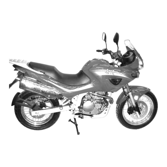
Photo of Complete Vehicle:
Engine Number Position:
Engine
Number
1
Overview
Engine Number Position
Frame Number Position:
Name Plate
-1-
Bar Tool
Maintenance Period Table
Wiring Diagram
Symbol Descriptions
Frame
Number
Name Plate
Position:
Overview
Advertisement
Table of Contents

Summary of Contents for Jialing-Gespann JH600
- Page 1 Overview JH600 Maintenance Manual Overview Engine Number Position Bar Tool Maintenance Precautions Maintenance Period Table Technical Data of Main Performance Wiring Diagram Standard Torque Values Symbol Descriptions Engine Number Position Photo of Complete Vehicle: Frame Number Position: Frame Number Engine Number Position:...
-
Page 2: Maintenance Precautions
Overview JH600 Maintenance Manual Maintenance Precautions 1. Use only the spare parts, fittings, lubricating oil and other auxiliary materials produced, recognized or recommended by China Jialing Industrial Co., Ltd. (Group). Using spare parts not conforming to the “Jialing” specifications or requirements may cause damage to the motorcycle. - Page 3 Overview JH600 Maintenance Manual 8. Before operating, always remove the negative (-) end of the battery first and take care to prevent the wrench or the like from touching the frame. After operating, reconfirm all the connections, fixings and junctions. If the battery is already removed, connect the positive (+) end first.
- Page 4 Overview JH600 Maintenance Manual The connector shall be fully inserted in place. For a connector with lock, confirm whether the Crackle lock is completely fixed. Make sure the harness is not falling off Make sure the plastic jacket of the connector is securely covering the connector without scaling off.
- Page 5 Overview JH600 Maintenance Manual The wire harness shall be clamped at the position without contacting a part that generates Do not touch! high temperature. The wire harness shall be clamped at the position without contacting the edge or sharp corners of the vehicle body.
- Page 6 Overview JH600 Maintenance Manual Do not mount wire harness with it twisted. 15. When wiring, note when turning it leftwards or rightwards to the limit position, the wire harness shall not be tightened up or slackened, and make sure there is no significant bending, pressing, intervening of marginal parts.
- Page 7 Overview JH600 Maintenance Manual Technical Data of Main Performance Item Data Length 2,210mm Width 860mm Height 1,330mm Dimension Wheelbase 1,470mm & Weight Min. ground clearance 200mm Complete vehicle weight Non-loaded weight: 195kg, Curb weight: 210kg, Fully loaded weight: 390kg Frame type...
- Page 8 Overview JH600 Maintenance Manual Item Data Clutch Wet clutch, coil clutch, paper friction wafer Clutch operating system Manual mechanical Variable speed gear 5-speed constant mesh Primary reduction ratio 2.345 Ⅰ Ⅰ Ⅰ Ⅰ 2.571 2.571 2.571 2.571 Transmission gear ratio Ⅱ...
-
Page 9: Standard Torque Values
Overview JH600 Maintenance Manual Standard Torque Values ENGINE Thread Torque value Item Quantity diameter Thread locker (N.m) (mm) Cylinder head connecting bolt 10~14 Cylinder bolt 48~52 Valve adjusting screw nut 7~11 Timing driven sprocket bolt 10~14 Rocker-arm shaft cover 24~28... - Page 10 Overview JH600 Maintenance Manual Vehicle body Thread diameter Torque value Thread Item Quantity (mm) (N.m) locker Front wheel spindle 50~60 Front vibration damper plate 8~12 Real wheel spindle nut 80~100 Rear fork shaft nut 60~70 Engine hanging bolt 39~49 25~35 Steering handle set bolt 20~30...
- Page 11 Overview JH600 Maintenance Manual Bar Tool Special Service Tools (SST) Tool Name Number Diagram Reference sections Counter shaft oil seal guide F02F000001 Rotor fastening tool F02F000002 Sprocket fastening tool F02F000003 Variable-speed shaft oil seal F02F000004 8、10 guide Piston sliding scale base...
- Page 12 Overview JH600 Maintenance Manual (Continued) Special Service Tools (SST) Rotor extractor F02F000029 Valve dismantling tool Gearshift drum oil seal guide F02CF000001 Spoke nut fastening tool X02F000001 Special socket for adjusting nut X02F000002 Rear damper adjusting wrench X02F000003 Special socket X02F000004...
- Page 13 Overview JH600 Maintenance Manual General-purpose Tools (Reference) Reference Tool Name BRIEF DESCRIPTION sections T-type wrench 8# Ultra thin T-type wrench 9# T-type wrench 10# T-type wrench 12# T-type wrench 13# T-type wrench 14# T-type wrench 15# Hexagonal socket 8 1/4″ joint, overall length 23mm Hexagonal socket 10 1/4″...
- Page 14 Overview JH600 Maintenance Manual (Continued) General-purpose Tools (Reference) Ratchet wrench 12.7 12.7mm joint Ball point Allen wrench Standard length, metric system, 1.5, 2, 2.5, 3, 4, 5, 6, 8 and 10mm, 9-Pc, 1 set Ball point Allen wrench Shortened length, metric system, 1.5, 2, 2.5, 3, 4, 5,...
-
Page 15: Maintenance Period Table
Overview JH600 Maintenance Manual Maintenance Period Table Maintenance times Odometer km (Remark 2) Period 2000 4,000 8,000 12,000 Remarks Maintenance Items Fuel system passage Fuel precision filter Replace for every 15000km driving Throttle operating system Throttle valve body Air filter element... -
Page 16: Wiring Diagram
Overview JH600 Maintenance Manual Wiring Diagram -16-... - Page 17 Overview JH600 Maintenance Manual Clutch handle seat leads Magnified view of Part A Right switch leads Instrument connecting wire Left combination switch leads Main cable Left turn lamp connecting wire Right switch leads Right turn lamp connecting wire Vehicle speed sensor leads...
- Page 18 Overview JH600 Maintenance Manual Magnified view of Part B Starting motor connecting wire ( - ) Main cable components Magneto leads Water temperature sensor connecting wire Rear brake switch leads Starting motor connecting wire ( + ) Shift position switch leads...
- Page 19 Overview JH600 Maintenance Manual Magnified view of Part D Starting relay Accumulator Headlight controller connecting wire ( + ) ECU controller & patch plug Flasher Fuel pump relay Rear position lamp connecting Complete Accumulator connecting wire ( - ) wire (Main cable)
- Page 20 Overview JH600 Maintenance Manual Magnified view of Part F Speed sensor connecting wire Phase sensor Thermoswitch connecting wire (Main cable) Intake negative pressure transducer Water temperature sensor Throttle position sensor patch plug -20-...
- Page 21 Overview JH600 Maintenance Manual Magnified view of Part G Vehicle speed sensor leads Phase sensor connection Front brake fuel tube -21-...
-
Page 22: Symbol Descriptions
Overview JH600 Maintenance Manual Symbol Descriptions Meanings of various symbols in this manual: Explanation: Measures to be prompted during operating, inspecting and maintaining. NOTICE: Special instructions or disposal measures given to prevent motorcycle from being damaged. WARNING: Special instructions or measures given to avoid serious damages or personal injuries.
Need help?
Do you have a question about the JH600 and is the answer not in the manual?
Questions and answers