Table of Contents
Advertisement
Quick Links
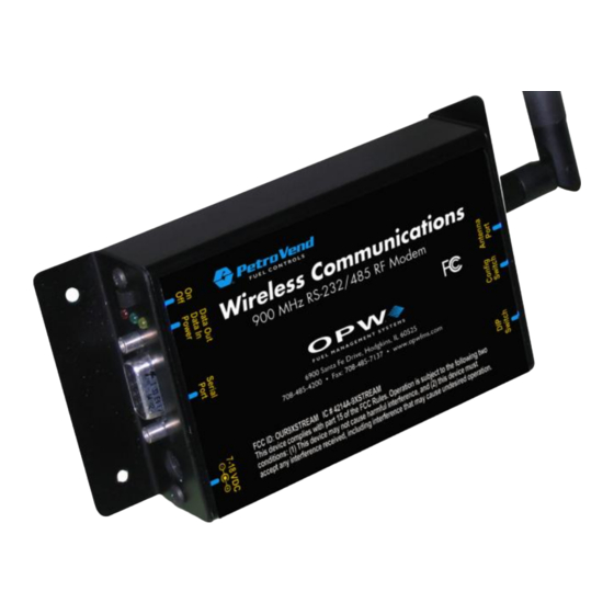
Wireless Petro-Net Modem
www.opwglobal.com
Central Technical Support Number:
Calls outside US and Canada:
Hours:
Monday through Friday, 7:00 am to 6:00 pm, US CST
1-877-OPW-TECH (877-679-8324)
1-708-485-4200
Fax:
1 (800) 421-3297
®
Document #:
M00-20-7074 Rev. 005
Issue Date:
December 14, 2011
Supersedes:
Rev. 004
Advertisement
Table of Contents
Troubleshooting

Related Manuals for OPW Wireless Petro-Net Modem

Summary of Contents for OPW Wireless Petro-Net Modem
- Page 1 ® Wireless Petro-Net Modem www.opwglobal.com Central Technical Support Number: 1-877-OPW-TECH (877-679-8324) Document #: M00-20-7074 Rev. 005 Calls outside US and Canada: 1-708-485-4200 Fax: 1 (800) 421-3297 Issue Date: December 14, 2011 Hours: Monday through Friday, 7:00 am to 6:00 pm, US CST Supersedes: Rev.
- Page 2 Product selection should be based on physical specifications and limitations and compatibility with environment and material to be handled. OPW makes no warranty of fitness for a particular use. All illustrations and specifications are subject to change at any time, and models may be discontinued at any time, in either case, without notice or obligation.
-
Page 3: Table Of Contents
2.2.2 Increasing Antenna Gain ........................ 8 2.2.3 Mounting Considerations ........................ 9 Typical Installations for the Wireless Petro-Net Modem® ................10 Typical Installations ..........................10 FIT-Mounted 6 in antenna ........................10 FIT with Remote Antenna (recommended) ................... 12 Multiple FITs (Networking) ........................12 FSC with Remote Antenna (Recommended by Manufacturer) ............. - Page 4 List of Figures Figure 1-1 Wireless Modem ____________________________________________________________ 5 Figure 2-1 Basic Communication System _________________________________________________ 6 Figure 2-2 Fresnel Zone ______________________________________________________________ 7 Figure 2-3 Physical Obstructions Overcome by Antenna Height ________________________________ 7 Figure 3-1 FIT-Mounted Modem Power Supply ____________________________________________ 10 Figure 3-2 FIT-Mounted Modem: Inside View _____________________________________________ 11 Figure 3-3 FIT Remote Antenna: Outside View ____________________________________________ 11 Figure 3-4 Remote Directional Antenna __________________________________________________ 12...
-
Page 5: Introduction
These instructions explain setting up the modem hardware, testing the range of the radio link, some advanced (but optional) configuration possibilities and some tips for better operation. Some installations may not be suitable for Wireless Communications. Contact OPW-FMS technical service for site survey and testing information if you are unsure of your potential installation site. -
Page 6: Pre-Installation Considerations
Conducting a Site Survey Before you decide to install the Wireless Petro-Net Modem, you must first make sure that it will work at the desired location. Communication systems have several components that should be looked at in each system: ... -
Page 7: Figure 2-2 Fresnel Zone
Various data points were inserted into Fresnel Zone formulas to provide some points of reference. The following table provides approximate Fresnel Zone diameters at 1,000 ft (304.8 m) and 1-mile (1.6 km) ranges. OPW does not recommend a distance greater than 5,000 feet (1524 m). www.opwglobal.com Document #: M00-20-7074 Rev. -
Page 8: Increasing Antenna Gain
Table 2-1 Fresnel Zone Diameters Required Fresnel Zone Diameter Required Fresnel Zone Diameter Range Distance (900 MHz Radios) (2.4 GHz Radios) 1000 ft. (300 m) 16 ft. (7 m) 11 ft. (5.4 m) 1 mile (1.6 km) 32 ft. (12 m) 21 ft. -
Page 9: Mounting Considerations
2.2.3 Mounting Considerations When mounting an antenna, care should be taken to make sure it is as far away from metal objects as possible. If nearby metal gets too close to an antenna, it has the potential to interfere with the way the antenna radiates and may cause some undesirable results. -
Page 10: Typical Installations For The Wireless Petro-Net Modem
3. Typical Installations for the Wireless Petro-Net Modem® ® This section covers the various mounting and wiring instructions for typical Wireless Petro-Net Modem installations. Typical Installations ® The Wireless Petro-Net Modem can be set up to work with various installations: ... -
Page 11: Figure 3-2 Fit-Mounted Modem: Inside View
Figure 3-2 FIT-Mounted Modem: Inside View Place the modem on the bottom of the FIT cabinet, connect the power and Petro-Net connectors. 10. Route the 1-foot antenna cable through the .375-inch hole to the .25-inch hole in the pedestal. 11. Seal the hole in the FIT with silicone. Figure 3-3 FIT Remote Antenna: Outside View www.opwglobal.com Document #:... -
Page 12: Fit With Remote Antenna (Recommended)
FIT with Remote Antenna (recommended) ® The Wireless Petro-Net Modem can also be set up with a remote antenna. For remote antenna mounting, attach the directional antenna to a pole or other surface using the supplied mounting brackets. Connect the 20- foot antenna cable to the modem or to the 1-foot cable in the FIT. -
Page 13: Fsc With Remote Modem
FSC with Remote Modem In areas where the FSC does not have a direct line-of-site with the modem and the antenna cable is too short it is necessary to use a remote modem. Extend the Petro-Net cable to position the modem where desired (1,000 feet maximum). Mount the modem in a secure location (or enclosure) and attach the 20-foot antenna cable to the modem. -
Page 14: Automated Tank Gauge Console
Automated Tank Gauge Console A wireless modem is connected to the VSmart Module to provide wireless communication option between the VSmart and the SiteSentinel® iSite™. The wireless modem should ideally be placed in an area where there is line-of-sight to the Console. Another modem is then wired to the SiteSentinel® iSite™ Console’s RS-485 port. The Wireless option will not communicate through metal buildings. -
Page 15: Sitesentinel® Isite™ With Vsmart In A Building
3.8.2 SiteSentinel® iSite™ with VSmart in a Building It is highly recommended that wireless Petro-Net installations are subjected to a site survey prior to installation in order to identify potential interference problems. www.opwglobal.com Document #: M00-20-7074 Rev. 005 Page 15 of 32... -
Page 16: Communication
Communication After determining the range of the modems, you can permanently install and wire the remote station modem. Polarity is critical with all RS-485 communications. Petro-Net Terminal 1 goes to pin 8 on the modem, and Terminal 2 goes to pin 2 on the 9-pin modem connector. Both modems are wired the same. Use the supplied Petro-Net connector;... -
Page 17: Fsc Installation Location Wiring
3.11 FSC Installation Location Wiring Place the modem on a table or shelf near the fuel site controller. Plug the power pack into a wall outlet. Connect the cable from the power pack to the modem. The indoor modem comes with a 6-inch antenna, for some applications this will work fine. When choosing a location, keep the REMOTE modem (at the fuel island) in mind. -
Page 18: Tank Gauge Installation Location Wiring
3.12 Tank Gauge Installation Location Wiring ® iSite™ wireless Petro-Net installation requires two wireless modems: The SiteSentinel 3.12.1 SiteSentinel® iSite™ Console Connection Connect the wireless modem two-wire connector to the console Petro-Net connectors. Black to terminal 1. White to terminal 2. www.opwglobal.com Document #: M00-20-7074 Rev. -
Page 19: Vsmart Connection
3.12.2 VSmart Connection Connect the VSmart wireless modem black and white wires to the Petro-Net terminals. Black to terminal 1. White to terminal 2. www.opwglobal.com Document #: M00-20-7074 Rev. 005 Page 19 of 32... -
Page 20: Xtend Modem Advanced Configuration
98, SE, 2000 or XP) and the software provided. DIP switch settings #1, #5, #6 ON to configure and run the range test; switch settings #5, #6 ON for OPW normal operation. If the site has communication interference, change the hopping channel on both modems to another channel. -
Page 21: Fsc To Multiple Fit Operation (3 Or More Wireless Modems)
FSC to Multiple FIT Operation (3 or More Wireless Modems) If you only have two (2) wireless modems, you do not have to configure the modems and you may proceed with the installation instructions; the modems are pre-configured for two (2) or less modems. -
Page 22: Fsc Modem Configuration
4.4.1 FSC Modem Configuration FSC Modem FFFF Must match all modems Figure 4-1 FSC Modem Configuration www.opwglobal.com Document #: M00-20-7074 Rev. 005 Page 22 of 32... -
Page 23: Fit #1 Modem Configuration
4.4.2 FIT #1 Modem Configuration FIT #1 Modem 1 (FIT #) 10 (FSC #) Must match all modems Figure 4-2 FIT #1 Modem Configuration www.opwglobal.com Document #: M00-20-7074 Rev. 005 Page 23 of 32... -
Page 24: Fit #2 Modem Configuration
4.4.3 FIT #2 Modem Configuration FIT #2 Modem 2 (FIT #) 10 (FSC #) Must match all modems Figure 4-3 FIT #2 Modem Configuration www.opwglobal.com Document #: M00-20-7074 Rev. 005 Page 24 of 32... -
Page 25: Point-To-Point Operation (2 Wireless Modems)
Point-To-Point Operation (2 Wireless Modems) When configuring these modems with the XTC software, set DIP switches to #1, #5/#6 ON and all others OFF. For normal operation, #5/#6 ON, all the rest OFF. It does not matter which modem is connected to the FSC or the FIT. www.opwglobal.com Document #: M00-20-7074 Rev. -
Page 26: Modem #1 Configuration
4.5.1 Modem #1 Configuration FIT #1 Modem 1 (FIT #) A (10) Must match all modems Figure 4-4 Modem #1 Configuration www.opwglobal.com Document #: M00-20-7074 Rev. 005 Page 26 of 32... -
Page 27: Modem #2 Configuration
4.5.2 Modem #2 Configuration FIT #2 2 (FIT #) A (10) Must match all modems Figure 4-5 Modem #2 Configuration www.opwglobal.com Document #: M00-20-7074 Rev. 005 Page 27 of 32... -
Page 28: Operation And Troubleshooting
Set both Radio DIP switches to RS-232 mode: [Switch #1, #5, #6 up (ON) and the remaining switches are down (OFF)]. ® Connect Radio 1 to a PC using an RS-232 cable (included with Wireless Petro-Net Modem part numbers that end with an “-RA” suffix). -
Page 29: Range Test Setup
Range Test Setup Once you have completed your site survey, you must run a range test to verify the suitability of the site before installation. The range of a wireless modem varies with its mounting location, but can be up to a mile or more. To maximize range, survey the site. -
Page 30: Figure 5-4 Range Test Tab
Figure 5-4 Range Test Tab www.opwglobal.com Document #: M00-20-7074 Rev. 005 Page 30 of 32... -
Page 31: Switch Settings
What frequency am I using? ® The Wireless Petro-Net Modem comes in two varieties: 900 MHz and 2.4 GHz. The 900 MHz waves penetrate objects and travel better than their 2.4 GHz counterparts. If you are in the U.S., Canada, Australia or Israel, you are using the 900-MHz radios. -
Page 32: Opw Switch Settings
This can cause the antenna to operate inefficiently. It is best to allow at least several inches of separation between the antenna and other metal structures or objects. 5.4.1 OPW Switch Settings 1-watt modem (6 LEDs near connector). ...
Need help?
Do you have a question about the Wireless Petro-Net Modem and is the answer not in the manual?
Questions and answers