Advertisement
Advertisement

Summary of Contents for Alpha Marine Systems Alpha 3000
-
Page 2: Warranty Registration
Purchaser assumes the responsibility for proper installation of the p rod uct. If the pro duct i s no t i nsta lled by a n authorize d Alpha Marine Systems dealer,... -
Page 3: Table Of Contents
Table Of Contents Warranty Registration ..................3 Operation ......................4 Installation Planning ..................6 System Connection Notes ................7 Installation instructions .................. 8 -System installation ......................8 -Drive unit installation ..................... 11 -Compass installation ....................... 17 Maintenance and Troubleshooting ............... 20... -
Page 5: Operation
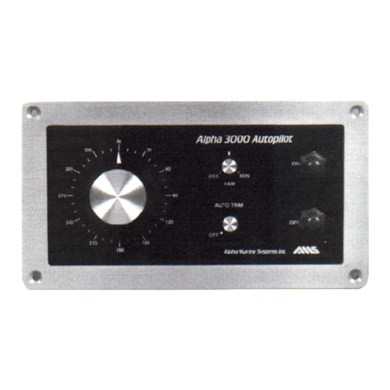
SECTION 1.0 OPERATION: Your autopilot has been specifically designed for ease and simplicity of operation and as a result has very few controls. The function and proper use of each of these controls are discussed below. POWER Pilot power is controlled by a pair of push buttons on the Control Unit. POWER ON switches the pilot On and selects that station for control in multiple station systems. - Page 6 COMPASS GAIN It is located on the rear of the main Control Unit. This adjusts the Compass for proper response on your vessel. To obtain maximum pilot performance, the compass gain should be adjusted until the vessel just stops “S” ing at the vessels top speed. Once set, no further adjustment should be required.
-
Page 7: Installation Planning
SECTION 2.0 INSTALLATION PLANNING Alpha Marine Systems autopilots are of a desirably modular design providing great installation flexibility. The installation should be planned so that the various units will be located within the vessel for optimum operational ease. Each unit, however, has its own installation limitations. -
Page 8: System Connection Notes
SECTION 3.0 SYSTEM CONNECTION NOTES Interconnection of various units should be done carefully, in accordance with interconnection diagrams (fig. 3.1 & 3.7) or damage to units may result. Particular attention and care should be exercised in connecting input power to ensure that polarity is observed and that the supply matches the 12 Volt DC Pilot requirements. -
Page 9: Installation Instructions
SECTION 3.1 AUTOPILOT INSTALLATION INSTRUCTIONS 1. Make a two-way powered run, in each direction mark Center Helm position (this is best done on a day with light winds and calm seas). Split the difference between these two marks with a third mark. This is operational Center Helm position. Retain this mark for use later in Drive Unit alignment. - Page 10 5. Route both the drive unit cables to the Control Unit and connect the rudder feedback cable (three wires) and the motor power leads per Figure 3.1 6. Measure the input power cable length needed to connect the Control Unit to the battery disconnect switch.
-
Page 11: Drive Unit Installation
SECTION 3.2 DRIVE UNIT INSTALLATION After completing section 3.1 proceed with the following Drive Unit installation. 1. Assemble the Morse Cable on the rudder drive link as shown in the assembly drawing Fig 3.4. 2. Adjust the threaded sleeve and stop nut to provide proper adequate latch engagement and disengagement. - Page 12 12. Reinstall the clamp and install the drive link screw. Secure with Lock-Tite™ 13. With the Morse Control engage the Drive Link with the Autopilot in the OFF position. Swing the helm slowly through the Autopilot operating range while observing the unit to ensure sufficient clearance.
-
Page 13: Compass Installation
SECTION 3.3 COMPASS INSTALLATION The installation of the pilot compass shares many things with the installation of any compass, except that visibility and access are of minimal importance. For optimum steering precision and heading accuracy, the compass should be mounted away from magnetic objects such as engines or current carrying wires, both of which can produce local magnetic fields. - Page 14 The Sensor must be more than one foot from the Electronics. The cable from the NOTE: sensor to the electronics must not be altered in any way. 6. Interconnect the units as shown in Fig. 3.7. a. Connect the Sensor to the Compass Electronics using the cable exiting the lower rear of the electronics housing.
- Page 15 However, whenever possible replacement parts should be obtained from the factory to ensure optimum performance. Some system components are available only from Alpha Marine Systems because of their custom nature. The mechanical drive unit has seals. However, the extending and retracting nature of the drive piston causes the internal volume of the unit to change, making a total seal impractical.
- Page 16 TROUBLESHOOTING GUIDE FOR THE AMS 3000 Symptom Problem and solution Pilot does nothing 1. Check power input and polarity Check fuse and replace if necessary Check connection to drive unit Check wiring for broken leads Sluggish response 2. Yaw setting at “MAX” a) Adjust knob towards “MIN”Wheel lock engaged Drive system jammed Drive unit damaged a) Return for repair Insufficient drive unit clearance...
Need help?
Do you have a question about the Alpha 3000 and is the answer not in the manual?
Questions and answers