
Summary of Contents for Mirrocle Bias-Differential Quad-Channel (BDQ) Amplifier 4.x
- Page 1 Mirrorcle Technologies, Inc. Bias-Differential Quad-Channel (BDQ) Amplifier 4.x Dr. Veljko Milanović Abhishek Kasturi Mirrorcle Technologies, Inc. February 2013 © 2012 - 2013 Mirrorcle Technologies, Inc. All rights reserved.
- Page 2 Overview Bias Differential Quad-channel (BDQ) Amplifier is a high voltage amplifier with two analog inputs and four high voltage analog outputs. It is designed and optimized for the driving of Mirrorcle Technologies MEMS mirrors at voltages up to 140V, whether from a National Instruments DAQ card or directly from BNC inputs.
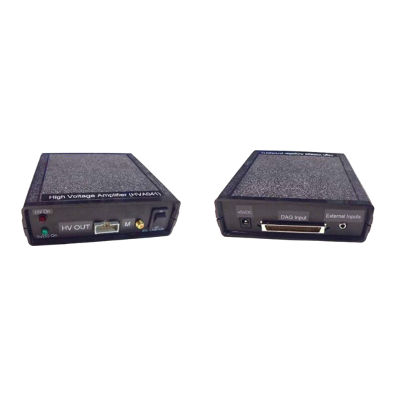
- Page 3 Features Two BNC analog inputs: -10V to +10V NI-DAQ card compatible, 68-pin connector input Low power, powered by NI-DAQ card when used or from a low power 5VDC adapter Four high voltage output channels, 0V-150V Outputs differential pairs of 7.5X amplified input voltages ...
- Page 4 Amplifier Inputs 68-Pin NIDAQ Input from compatible National Instruments DAQ Cards External Inputs: Using a Power supply 5VDC 3.5mm TRS to Dual RCAF breakout, and a RCA to BNC adaptors for input signals © 2012 - 2013 Mirrorcle Technologies, Inc. All rights reserved.
- Page 5 Specifications – DAQ Input 68-pin SCSI connector compatible with many NI-DAQ cards (e.g. PCI-6221) Cable is not provided Input voltage range: -10V to 10V on AO0 (X) and AO1 (Y) Input impedance ~ 16 k X input: DAQ AO0, Y input: DAQ AO1, HV Enable: DAQ P1.0 ...
- Page 6 Specifications – External Input Input voltages -10V to 10V on X and Y bi-polar channels Input voltage range: -10V to 10V on AO0 (X) and AO1 (Y) Input impedance ~ 16 k X input: red BNC, Y input: white BNC ...
- Page 7 Bi-Directional Driving with Unipolar Voltages HV_B is high HV_A is high HV_A is low HV_B is low Mirror rotates in Mirror rotates in X- direction X+ direction Analog Input X © 2012 - 2013 Mirrorcle Technologies, Inc. All rights reserved.
- Page 8 Specifications - Output X+ output voltage = Vbias + 7.5*X X- output voltage = Vbias – 7.5*X Y- output voltage = Vbias + 7.5*Y Y+ output voltage = Vbias – 7.5*Y Slew Rate: 10 V/ µ ...
- Page 9 Output Connector Pinout and Functions Input: 8 ‐ Pin Header Pin Name Description HV_A (X+) High Voltage Output for Channel X+ Ground HV_B (X‐) High Voltage Output for Channel X‐ Ground HV_C (Y‐) High Voltage Output for Channel Y‐ Ground HV_D (Y+) High Voltage Output for Channel Y+ Ground No Connection No Connection © 2012 - 2013 Mirrorcle Technologies, Inc. All rights reserved.
-
Page 10: Specific Instructions
SPECIFIC INSTRUCTIONS BDQ PicoAmp4.x... - Page 11 Bringing up BDQ Amplifier Turn on the BDQ Amplifier by connecting the 5V supply. Connect the BNC inputs to a source. Prior to enabling high voltage, send mirror origin voltage of 0V to analog inputs X and Y. To enable the high voltage, set the High Voltage switch to the ON position. The red LED will indicate when the high voltage is on.
- Page 12 Shutting down BDQ Amplifier 4.x Send mirror origin voltage of 0V to analog inputs X and Y. Disable the high voltage by setting the High Voltage switch to the off position. WARNING: DO NOT UNPLUG OR DISABLE ANALOG INPUTS PRIOR TO THIS STEP TO AVOID APPLYING 0V TO ACTIVE ANALOG INPUTS.
- Page 13 Safe Range of Input Voltages Each Mirrorcle MEMS Mirror datasheet specifies the maximum voltage rating (V ) for a given device on page 1, e.g. 125V. To obtain analog input voltage range: Maximum V = (V / 7.5) – 9.333 Minimum V = 9.333 –...
- Page 14 Internal user-adjustable points bias-regulating pot (currently set for 70V output bias) Power supply input © 2012 - 2013 Mirrorcle Technologies, Inc. All rights reserved.
- Page 15 Adjusting bias voltage Connect BNC inputs to amplifier Apply 0V to both BNCs or leave them both unplugged Ensure high voltage is ON by the Enable Override switch on front panel Monitor an output pin (e.g. X+) and turn bias-adjusting ...
- Page 16 Modulation / Trigger Output Modulation (M) output Synchronous laser modulation, triggering, etc, can ONLY be used with the DAQ input and if your NI-DAQ card has “correlated DIO” feature. SMA connector is directly connected to DAQ card’s P0.0 DIO. ...
Need help?
Do you have a question about the Bias-Differential Quad-Channel (BDQ) Amplifier 4.x and is the answer not in the manual?
Questions and answers