Table of Contents
Advertisement
Quick Links
Advertisement
Table of Contents

Summary of Contents for AsuraCPRNT Terminal
- Page 1 AsuraCPRNT Hardware Manual Rev. 1.3...
- Page 2 This Class A digital apparatus complies with Canadian ICES-003. The above statement applies only to printers marketed in Canada. Trademark acknowledgments AsuraCPRNT: Star Micronics Co., Ltd. Notice • All rights reserved. Reproduction of any part of this manual in any form whatsoever, without STAR’s express permission is forbidden.
- Page 3 Caution Symbol These symbols are located near the thermal print head. Because the thermal print head is hot immediately after printing, do not touch it. Static electricity can damage the thermal print head. To protect the thermal print head from static electricity, do not touch it. This symbol is located near the cutter.
-
Page 4: Table Of Contents
3-3. Connecting to the Host PC ..............................11 3-4. Connecting the Power Cable ..............................12 3-5. Turning the Power On and Off .............................. 13 3-6. AsuraCPRNT Setup ( Admin Option ) ..........................14 3-7. Connecting to Peripheral Devices ............................15 3-8. Setup Precautions ..................................17 4. -
Page 5: Unpacking And Installation
1. Install on a sturdy, level surface where the AsuraCPRNT will not be exposed to vibrations. 2. Locate the AsuraCPRNT near a power outlet so that the power cable can be easily accessed when needed. 3. Do not use the same outlet that is already being used by copiers, refrigerators, or other devices that generate electrical noise. -
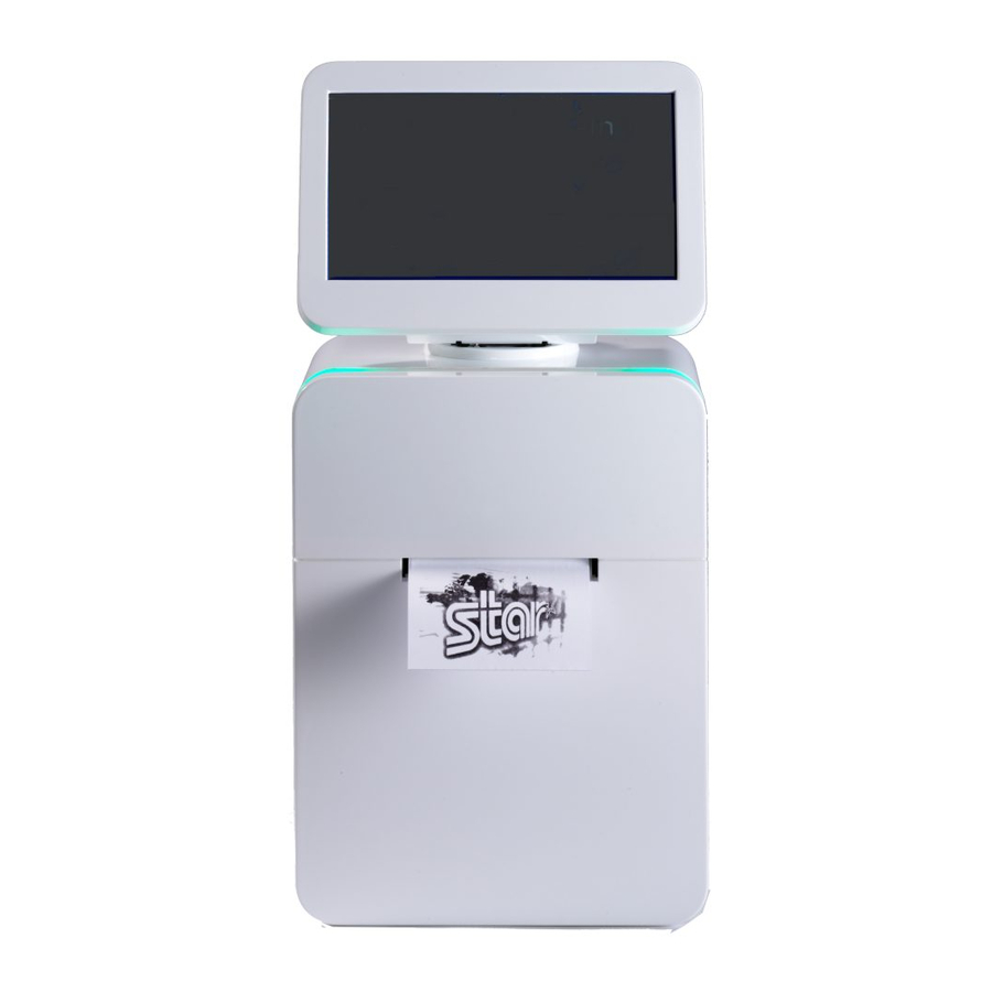
Page 6: Parts Identification And Nomenclature
Touch screen When the AsuraCPRNT is started, the home screen is displayed. Touch the screen to operate the AsuraCPRNT and applications. The full color LED indicates the status of the AsuraCPRNT and any errors that occur. Front panel Open to replace paper. - Page 7 Max 180° 15 16 100/10BASE MIC OUT DC24V Power button Turns on the power of the AsuraCPRNT. Starts the Admin Option when a system is running. Speaker Sounds can be emitted based on the application settings. AC inlet Connects to the power cable.
-
Page 8: Setup
① Check that the loading position matches the paper roll width using the marks at the positions in the left figure below. (Load 57.5-mm width paper at the 58 position.) With the AsuraCPRNT placed flat as shown in the right figure below, insert the paper roll guide so that it slides into the slot in the AsuraCPRNT. -
Page 9: Loading A Paper Roll
2 Open the front panel by grasping both sides of the front panel with your fingers, pull the cover open lever, and open the printer cover. Cover open lever 3 Load the paper roll into the AsuraCPRNT in the direction indicated by the figure, and pull the leading edge of the paper straight toward you. Note: •... - Page 10 4 Press on both sides of the printer cover to close it. After the printer cover is closed, the printer performs initial operations (from paper feeding to paper cutting). Do not open the printer cover until the initial operations are complete. 5 Remove the paper that was cut, and press on both sides to close the front panel.
-
Page 11: Connecting To The Host Pc
Printer cables are sold separately. Obtain a cable that matches the specifications. Because the appropriate interface cable depends on the system that you are connecting the AsuraCPRNT to, contact the dealer where you purchased the product if you are unsure about what cable to use. -
Page 12: Connecting The Power Cable
3-4. Connecting the Power Cable Note: Before connecting or disconnecting the power cable, make sure that the AsuraCPRNT and all the devices connect- ed to it are turned off. ① Connect the power cable. Note: Use the supplied power cable only. -
Page 13: Turning The Power On And Off
♦ Admin Option Press the Power button on the rear of the AsuraCPRNT when a system is running, to display the Admin Option screen. Select [Shutdown] at the lower left on the Admin option screen, to turn off the AsuraCPRNT power. -
Page 14: Asuracprnt Setup ( Admin Option )
3-6. AsuraCPRNT Setup ( Admin Option ) To make the settings below, start the Admin Option by pressing the Power button when a system is running. ♦ Mechanism ● Lock Paper Cover / Unlock Paper Cover ● Print Test Page ●... -
Page 15: Connecting To Peripheral Devices
(sold separately). Power up to 5V/0.5A can be supplied at each port. ① Connect the connector of the USB device cable to the USB connector (host) on the rear of the AsuraCPRNT. ② As shown in the figure, pass the cable through the cable hook to hold it in place. - Page 16 3-7-3. Microphone and Speakers ●Microphone A microphone can be connected to the microphone input jack. The microphones below can be used with this product. • Monaural condenser microphone • 3.5-mm diameter mini-jack type 100/10BASE MIC OUT DC24V ●Speaker (LINEOUT jack) A speaker with a built-in amplifier can be connected.
-
Page 17: Setup Precautions
When the product includes an AC cable set, the included power cable has been designed specifically for the prod- uct. Make sure that the AsuraCPRNT and the PC are turned off and unplugged from their AC outlets before you connect or disconnect the cables. - Page 18 The printing quality and the thermal print head's service life cannot be guaranteed if paper other than the recommended thermal paper is used. In particular, thermal paper containing Na+, K+, or Cl- can significantly reduce the service life of the thermal print head.
-
Page 19: Mounting Of Other Parts
4. Mounting of Other Parts The parts below can be used by mounting to this product. Use the parts as required for your application. • Base stand (accessory) This is used when mounting the product to a stand. Also, the rubber feet supplied with the base stand can be attached for using with- out attaching to a stand. - Page 20 • When using the supplied nuts and screws to secure the base stand ① The screw holes for installing the base stand are compatible with holes having an approximate diameter of 4.5 mm and located at 75x75 mm or 100x100 mm intervals. ②...
- Page 21 ② As shown in the figure below (left), fit the main unit onto the supports of the base stand. When mounting, be careful that cables and other objects do not get stuck in between. Also, if a hole for routing cables is made in the installation stand, the cables can pass through the base stand hole as shown in the figure below (right) when mounting.
-
Page 22: Mounting To A Wall Mount Fixture (Not Included)
4-2. Mounting to a Wall Mount Fixture (Not Included) The AsuraCPRNT can be mounted on the wall by using a wall mount fixture (Karatec MF3210 not included) compliant with the VESA mounting interface standards (75x75 mm interval). ① Remove the power cable from the product. - Page 23 ⑤ Mount the wall mount fixture by following the instructions in the wall mount fixture manual. • Usage example Rear case Chassis screw drilling Wall Material Wall mount fixture Cautions when mounting: • When mounting to a wall, be sure to ask a contractor specialized in this type of design, building, and construc- tion to perform the work.
-
Page 24: Installing A Microsd Card (Not Included)
4-3. Installing a microSD Card (Not Included) A microSD card (not included) can be installed in this product for storing user data. • Compatible microSD card specifications: 32 GB capacity max. Supports Class 2, 4, 6, 10 ① Remove the power cable from the product. ②... -
Page 25: Attaching A Security Cable (Not Included)
4-4. Attaching a Security Cable (Not Included) A security cable (not included) that supports security slots (such as Kensington lock) can be attached to this product. ① Remove the power cable from the product. ② Remove the two screws, and take off the rear case. Rear case Security cable Security slots... -
Page 26: Msr / Bcr
5. MSR / BCR 5-1. MSR This function is for reading data on the magnetic stripe card. Data can be read from magnetic cards that meet the following specifications. ● Magnetic card conforming to JIS X6302-1998. * ● Magnetic card conforming to ISO/IE C7810,7811. * It is impossible to read the magnetic stripe on surface of card (JISII) conforming to JIS X6302-1998. - Page 27 Follow the steps below to change the BCR light position. Note the following precautions during changing the BCR Light Position. ● When changing the position of the BCR light, or attaching the optional unit to AsuraCPRNT, make sure you turn off AsuraCPRNT and unplug the power cable.
- Page 28 3 Remove the screws securing the BCR unit, and then remove the BCR unit from the body of the product. Upper screw hole Upper boss 4 Check the positions of the BCR unit screw holes and the bosses for the attachment location, attach the BCR unit, and then secure with the screws (x2).
-
Page 29: Led Indicators
Remove the jammed paper to recover the printer. ◇ Note 1: When an error occurs, all received data in the AsuraCPRNT is discarded. 2: When paper is jammed, turn off the printer, remove the jammed paper, and then turn the power on again. For details, see section , “7-2. -
Page 30: Unrecoverable Errors
If an unrecoverable error occurs, turn off the AsuraCPRNT, perform the recovery procedure, and then turn the Asura- CPRNT back on. If the same error occurs after you turn the AsuraCPRNT back on, the product needs to be repaired. Contact the dealer where you purchased the product. -
Page 31: Preventing And Removing Paper Jams
7-1. Preventing Paper Jams When you load the paper roll into the AsuraCPRNT, do not pull out the end of the paper at an angle. If you close the printer cover with the paper roll skewed, paper jams and other problems can occur. -
Page 32: Releasing The Cutter Lock
If the cover lock function is used, release the cover lock by the admin option before shutting off the power. See “3-6. AsuraCPRNT Setup ( Admin Option )” for the details of the admin option. ② Remove the cutter cover. -
Page 33: Maintenance
As a general guideline, perform maintenance every six months. Note: Before performing maintenance, be sure to unplug the AsuraCPRNT power cable from the outlet. 8-1. Thermal Head To remove the blackened paper dust that has accumulated on the surface of the thermal head, wipe it clean with a cotton swab (or soft cloth) dipped in alcohol (ethanol, methanol, or isopropyl). -
Page 34: Sensors And Their Surrounding Area
8-4. Sensors and their Surrounding Area Remove any debris, dust, paper particles, and other objects adhering to the sensors. Pay particular attention to the paper empty sensor and black mark sensor. Detection will not be performed properly if these sensors are dirty. Using a brush or similar tool can make the cleaning process relatively easy. - Page 35 URL: http://www.starmicronics.com/support/...
Need help?
Do you have a question about the Terminal and is the answer not in the manual?
Questions and answers