
Summary of Contents for Z-Band video Gen 4 “GigaBUD 1000”
-
Page 1: Installation Guide
Gen 4 “GigaBUD 1000” Video Distribution System Installation Guide Version 5.2 October 2014... -
Page 2: Important Safety Instructions
“GigaBUD 1000” Installation Guide IMPORTANT SAFETY INSTRUCTIONS: WARNING: Failure to follow this guide can lead to malfunction of the system and invalidation of the warranty SHOCK HAZARD The “GigaBUD 1000”, along with all of the components, are designed for indoor use ONLY. Direct exposure to moisture must be avoided. -
Page 3: General System Overview
“GigaBUD 1000” Installation Guide General System Overview The Z-Band Video Distribution System is designed to distribute the full spectrum (54 to 860 MHz) of high quality, Analog and/or Digital Radio Frequency (RF) Video from a CATV direct feed or a Headend (Sources) to Televisions and/or Set-top- boxes (Receivers) in a building, campus or metropolitan area. - Page 4 “GigaBUD 1000” Installation Guide Depicts a Basic Layout of a System with a Singlemode Fiber Backbone Figure 1 Depicts a Basic Layout os a System with a Co- Depicts a Basic Layout of a System with a Coaxial Backbone Notice that the Horizontal is the same in the Figure 1 and Figure 2 options.
- Page 5 “GigaBUD 1000” Installation Guide Layout of Basic System with Shared Sheath for Video and IP Figure 3 Allows the RF Video (on Pins 7 & 8) and the IP (on Pins 1, 2, 3, 6) to be com- bined at the GigaBUD 1000 and Separated at the GigaBOB. A port from the Ethernet Switch is plugged into the top row (Aux) of the GigaBUD and is com- bine with the RF Video that is on the bottom row.
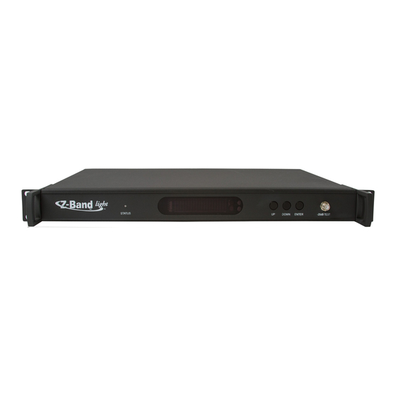
- Page 6 “GigaBUD 1000” Installation Guide Front & Rear View of Z-Band Light TX Video Sources CATV/Headend 20dBmV + or –5 Status Light Fiber Output to Fiber Splitter Figure 5 The Z-Band Light Transmitter accepts the coax Source signals at the “F” connector input.
- Page 7 “GigaBUD 1000” Installation Guide “GigaBUD 1000” Views IP/RF Output IP/AUX Input Front View (12 Port) GigaBUD 1000 Video Hub RF VIDEO BROWSER PORT POWER MASTER SLAVE STATUS Front View (24 Port) Video Hub GigaBUD 1000 RF VIDEO BROWSER PORT POWER MASTER SLAVE STATUS Rear View (12 &...
-
Page 8: Front View
“GigaBUD 1000” Installation Guide GigaBOB Views Rear View Front View To TV or Set-top Box Wall Mount Balun with Diplexer Auxiliary/IP Out Horizontal Cable In From Wall Outlet Figure 7 Auxiliary/IP Out Horizontal Cable In From Wall Outlet Free Hanging Balun (Avail. -
Page 9: Installation Requirements
“GigaBUD 1000” Installation Guide Installation Requirements: Category Cable: Category 5E or better cable for horizontal wiring plant per ANSI/TIA-568-C Series Standard Category patch cables Category cable must be matched throughout a Z-Band System. Do not use a mixture of different cables Coax Cable: ... -
Page 10: Installation Recommendations
“GigaBUD 1000” Installation Guide Installation Recommendations: Category Cable: Category 6 or better cable for horizontal wiring plant per ANSI/TIA-568-C Coax Cable: Terminate with Compression Connectors RF Signal and Fiber Test Meters: RF Signal Meter Fiber Optic Power Meter Televes Advanced Fiber Solutions H30 SERIES... - Page 11 “GigaBUD 1000” Installation Guide Interconnecting GigaBUD 1000s in the Backbone When a GigaBUD 1000 receives a video input signal from the Source it is automatically designated as a Master, and becomes a Level 1 device. This is true if the Source connection is a Coax connection to the “CATV” input of a GigaBUD 1000 or a Fiber connection to the “Fiber Input”...
- Page 12 “GigaBUD 1000” Installation Guide Example of Fiber Master & Coax Backbone in a closet -1 to –4dBm Level 1 Level 2 Level 2 Level 2 Figure 10 Figure 10 depicts the Cascade connections that are typical in a closet containing a Fiber Master.
- Page 13 “GigaBUD 1000” Installation Guide Fiber Backbone to Every Closet Figure 12 depicts the fiber connections from a Z-Band Light Transmitter to a Fiber Master in each closet of a building. Figure 12 www.z-band.com/866-902-2606...
- Page 14 “GigaBUD 1000” Installation Guide Coax Backbone to Every Closet Figure 13 depicts the coax connections from a non-fiber GigaBUD 1000 Master to Level 2 Satellite devices in each closet of a Building. IDF 3 IDF 4 IDF 2 IDF 1 IDF 5 Figure 13 www.z-band.com/866-902-2606...
- Page 15 “GigaBUD 1000” Installation Guide Fiber Backbone to Every Closet, Coax Backbone Cascade within the Closets Figure 14 depicts a typical Campus installation using a Fiber Backbone to each closet in multiple buildings, and Coax Cascades within each closet. Figure 14 www.z-band.com/866-902-2606...
- Page 16 “GigaBUD 1000” Installation Guide FRONT INDICATORS AND RED BUTTON ON REAR: Initial Power-Up GigaBUD 1000 Video Hub RF VIDEO BROWSER PORT POWER MASTER SLAVE STATUS All four lights indicate the System is searching for a source and whether it will be a Master or a Satellite unit.
- Page 17 “GigaBUD 1000” Installation Guide “GigaBUD 1000” FUNCTIONS: Satellite (Unlocked) GigaBUD 1000 Video Hub RF VIDEO BROWSER PORT POWER MASTER SLAVE STATUS The lights for this mode indicate that the unit is a Satellite unit. A blinking amber light means there is a RF signal on the “Cascade In”...
- Page 18 “GigaBUD 1000” Installation Guide SERVICE PROVIDER TO Non-Fiber GigaBUD INTERFACE: FIBER 90-264 VAC INPUT 47-63Hz 150W 2A Fuse CATV Inbound Cascade Cascade Outbound Analog 23dBmV Digital 17 to 20dBmV CATV / Headend Testing Point 1 X 2 Splitter Putting the splitter in the System will allow for reading the input signal level and quality (MER or C/N) without disconnecting the System.
- Page 19 “GigaBUD 1000” Installation Guide Bi-Directional CASCADE CONFIGURATIONS: Some installs will require a return path for video on demand and other special features. In the event that the system uses a DOCSIS or FSK return, it will be necessary to provide a Bi-Directional Cascade Backbone, as shown below.
Need help?
Do you have a question about the Gen 4 “GigaBUD 1000” and is the answer not in the manual?
Questions and answers