Table of Contents
Advertisement
Available languages
Available languages
Quick Links
Advertisement
Chapters
Table of Contents

Subscribe to Our Youtube Channel
Summary of Contents for Audio Contractor VAIE 2250
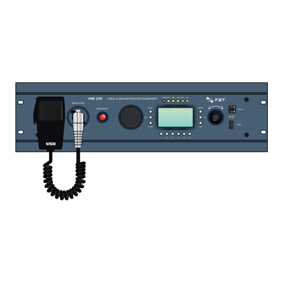
- Page 1 VAIE 2250 Voice Alarm Integrated Equipment MANUALE DI ISTRUZIONI OPERATING MANUAL Ver. 0.5.0.0 FBT ELETTRONICA S.p.A. - Via Paolo Soprani, 1 - ZONA IND. SQUARTABUE - 62019 RECANATI (MC) - ITALY TEL. 071750591 r.a. - FAX 0717505920 - P.O. BOX 104 - E-mail: info@fbt.it - www.fbt.it...
-
Page 2: Table Of Contents
INDICE DEI CONTENUTI AVVERTENZE Installazione Alimentazione e messa a terra Note di sicurezza INTRODUZIONE RIFERIMENTI NUMERATI Pannello frontale Pannello posteriore Pannello comandi DESCRIZIONE GENERALE Panoramica sul sistema Caratteristiche funzionali Caratteristiche tecniche CONNESSIONI E DIMENSIONAMENTO Collegamento dei diffusori Contatti d’ingresso locali Contatti d’uscita locali Collegamento degli ingressi audio Impianto a 12 zone... -
Page 3: Avvertenze
Evitare di racchiudere l’apparecchio in un mobile privo di aerazione o di tenerlo in prossimità di sorgenti di calore. Il VAIE 2250 può essere montato in rack standard FBT da 19” utilizzando le apposite staffe di supporto. -
Page 4: Introduzione
INTRODUZIONE Il VAIE 2250 è un sistema d’evacuazione vocale integrato che consente la diffusione della musica di sottofondo e delle chiamate (generali o di zona) senza interferire con le routine di diagnostica. Questo sistema è stato progettato per una facile installazione e per il funzionamento in una vasta gamma di applicazioni dove sono richiesti sia sistemi d’emergenza vocale che sistemi di diffusione sonora, nel rispetto degli standard di sicurezza... -
Page 5: Riferimenti Numerati
• Led SYS (giallo): segnalazione della condizione di Guasto di Sistema (System CPU Fault) in corso. • Led BATT (verde): segnalazione dell’alimentazione ausiliaria 24Vcc. • Led ON (verde): segnalazione del sistema VAIE 2250 acceso ed operativo. C10. Comando rotativo multifunzionale di selezione e regolazione. -
Page 6: Descrizione Generale
EN54-16, è continuamente monitorato al fine di segnalare tempestivamente eventuali anomalie. È possibile interconnettere 2 unità VAIE 2250 in modo da unire 2 sistemi da 6 zone e configurare un impianto fino a 12 zone totali, la linea di collegamento può... - Page 7 DESCRIZIONE GENERALE SISTEMA D’EVACUAZIONE 12 ZONE CON POSTAZIONI D’EMERGENZA REMOTE...
-
Page 8: Caratteristiche Funzionali
Possibilità di aggiungere un amplificatore esterno da 250W per aumentare la potenza dell’impianto. • Gestione automatica dell’amplificatore musica come riserva dell’amplificatore operativo (interno o esterno). • Possibilità di espandere il sistema fino 12 zone con una seconda unità VAIE 2250 remota. • Possibilità di collegare fino a 16 postazioni di chiamata. •... -
Page 9: Connessioni E Dimensionamento
Attenzione! Prima di collegare le linee è opportuno impostare correttamente la modalità operativa in base alla configurazione d’im- pianto. Fare riferimento alla Sezione “set > AMPLIFIER MODE” (par. 8.7.5). 5.1.1 Impianto da 250W totali a 100V - n°1 VAIE 2250 Installare solo diffusori sonori con traslatore per linee a 100Vtc. - Page 10 CONNESSIONI E DIMENSIONAMENTO 5.1.2 Impianto da 490W totali a 100V - n°1 VAIE 2250 con amplificatore esterno FBT dedicato (cod. MPA 5240) Installare solo diffusori sonori con traslatore per linee a 100V tc. Dimensionamento - Verifica della potenza di carico delle linee diffusori Misurare l’impedenza di ciascuna linea diffusori con un impedenzimetro a 1 kHz:...
-
Page 11: Contatti D'ingresso Locali
5.2.1 Contatti d’ingresso locali per sistema a 12 zone Le 2 unità VAIE 2250 interconnesse in modo da configurare un sistema a 12 zone, vengono considerate come 2 sistemi distinti. I contatti di attivazione della periferica esterna dovranno essere collegati separatamente a ciascuna unità VAIE 2250. -
Page 12: Contatti D'uscita Locali
OUT1 a OUT6 di un’unità VAIE 2250 non possono essere collegati insieme con i contatti di uscita di una seconda unità VAIE 2250. I contatti di uscita RELAY 1 e RELAY 2 di un’unità VAIE 2250 possono essere collegati ai RELAY 1 e RELAY 2 di un’altra unità VAIE 2250, in serie o in parallelo, in modo da raggruppare le attivazioni. -
Page 13: Collegamento Degli Ingressi Audio
Attenzione! Non collegare altre apparecchiature ai morsetti LINE dell’ingresso IN.2. Nota: in caso di sistema a 12 zone la sorgente PA che utilizza la precedenza su un VAIE 2250 non viene condivisa con l’altra unità VAIE 2250 e viene diffusa come sorgente “locale”. - Page 14 >VOX: OFF Nota: in caso di sistema a 12 zone l’ingresso di linea che utilizza la funzione VOX su un VAIE 2250 non viene condivisa con l’altra unità VAIE 2250 e viene diffusa come sorgente “locale””. Se necessario effettuare il collegamento in parallelo sull’ingresso IN 3 dell’altra unità...
-
Page 15: Impianto A 12 Zone
5.5.2 Assegnazione delle zone d’uscita ai comandi di selezione • Unità VAIE 2250 I 6 tasti numerici di selezione del pannello comandi di ciascun VAIE 2250 operano solo sulle proprie zone di uscita e le 2 unità operano sostanzialmente come 2 sistemi distinti da 6 zone ciascuno. - Page 16 I led di segnalazione della tastiera di selezione zone sono assegnati alle zone di uscita dell’impianto con riferimento all’unità VAIE 2250 di collegamento della postazione microfonica: - Il primo gruppo di Led dei tasti di selezione da n. 1 a n. 6 è assegnato alle zone di uscita dell’unità VAIE 2250 “Locale” alla quale la postazione stessa è collegata.
-
Page 17: Operatività E Nomenclatura
“Control Inputs” oppure da una Emergenza Manuale tramite operatore autorizzato. Durante lo “Stato di Allarme” le funzioni delle sorgenti musicali e delle sorgenti voce riferite allo Stato di Quiete non sono operative. In un sistema a 12 zone con 2 unità VAIE 2250 interconnesse lo “Stato di Allarme”... - Page 18 - Microfono di Emergenza (P.T.T.) collegato alla presa frontale MICROPHONE. - Postazione Microfonica di Emergenza collegata alla presa posteriore EMERGENCY UNITS. - Una delle sopracitate sorgenti VES (ALERT- EVAC – PTT – EMERG. UNITS) collegata all’unità VAIE 2250 remota, e attiva sull’unità VAIE 2250 locale attraverso l’interconnessione REMOTE LINK.
-
Page 19: Dotazioni E Caratteristiche Funzionali
-10db/+10dB rispetto al volume impostato per l’ingresso selezionato. Indipendentemente dall’impostazione manuale del monitor, il sistema VAIE 2250 utilizzerà l’altoparlante, con priorità assoluta, per la segnalazione acustica di guasto rilevato (beep). Il tono di segnalazione, verrà silenziato automaticamente se le condizioni di guasto terminano, inoltre, al fine di evitare inneschi per effetto Larsen, sarà... - Page 20 Led di segnalazione dello “Stato di Guasto” in corso. Indica che il sistema di diagnosi ha rilevato almeno una condizione di guasto, per l’unità VAIE 2250 in uno o per gli elementi diagnosticati collegati ad essa. In caso di condizione di guasto terminata, il led FAULT si spegne automaticamente e la scritta “RES”...
- Page 21 REMOTE LINK Uscita per il collegamento con unità VAIE 2250 remota. Consente di espandere il sistema, per configurazioni di impianto fino a 12 zone, tramite l’interconnessione di 2 unità VAIE 2250, con distanza di collegamento fino a 1 km. Presa RJ45 per collegamento con cavo CAT.
- Page 22 490W totali. Collegare l’uscita di potenza a tensione costante dell’amplificatore ai morsetti previsti per i segnali 0V-70V e 100V di una unità VAIE 2250. In caso di sistema a 12 zone con 2 unità VAIE 2250 interconnesse, non utilizzare un solo amplificatore di espansione per entrambe i VAIE 2250, ma installare eventualmente 2 distinti amplificatori ;...
-
Page 23: Struttura Dei Menu
7. STRUTTURA DEI MENU Il VAIE 2250 permette l’accesso alle funzioni del sistema tramite una serie di Pannelli di Gestione raggruppati, secondo tipologia operativa e destinazione d’uso, in Menu Opzioni accessibili dalla HOME; inoltre i seguenti Menu Opzioni sono stati assegnati a differenti livelli d’accesso, in riferimento alle varie circostanze che richiedono diversi gradi di competenza e di autorizzazione del personale preposto. - Page 24 STRUTTURA DEI MENU 7.1.2 Livello Base - IMPOSTAZIONI AUDIO Sulla schermata HOME , premere il tasto OK per selezionare la voce AUDIO SETTING ed accedere al menu relativo. Dal Menu AUDIO SETTING utilizzare la manopola a lato del display per scorrere tra le opzioni elencate e selezionare quella desiderata utilizzando il tasto OK.
- Page 25 STRUTTURA DEI MENU 7.1.5 Livello di Sistema - CONFIGURAZIONE Sulla schermata HOME , ruotare la manopola e quindi premere il tasto OK per selezionare la voce CONFIGURATION: per accedere al menu relativo è necessario inserire una password e quindi premere nuovamente il tasto OK. In alternativa premere ESC per Dal Menu CONFIGURATION utilizzare la manopola a lato del display per scorrere tra le opzioni elencate e selezionare quella desiderata utilizzando il tasto OK.
-
Page 26: Uso Del Sistema
Abilitazione dell’ingresso musicale verso il VAIE 2250 remoto In caso di sistema a 12 zone, con 2 VAIE 2250 interconnessi, è possibile abilitare l’ingresso selezionato per la sorgente musicale del proprio VAIE 2250 affinché possa essere riprodotto anche dal VAIE 2250 remoto. -
Page 27: Inizializzazione Dell'impianto
Percorso: HOME / CONFIGURATION / set> BACKGROUND TEST / 4-Power supply • Messaggi d’emergenza Caricare nella memoria residente del VAIE 2250 i file *.WAV previsti per i messaggi di ALERT e EVAC, come da indicazioni riportate nel paragrafo “MESSAGES” (vedi par. 8.7.3). -
Page 28: Menu
L’etichetta di stato (B) commuterà l’indicazione tra OFF (musica disabilitata) e ndB (musica ON e relativo volume d’uscita). Nota: Il sistema VAIE 2250 permette di effettuare annunci di servizio da parte di una sorgente PA sulle zone desiderate, mantenendo la diffusione della musica sulle altre zone non interessate dalla chiamata. Durante un’annuncio in corso, il display visualizzerà...: Impostazione Dei Parametri Audio Delle Sorgenti Bgm - Page 29 USO DEL SISTEMA 8.3.5 Pannello di controllo MUSIC-USB Pannello di controllo delle sorgenti musica, visualizzato nel caso di selezione della sorgente USB, premendo ciclicamente il tasto ESC si ha la commutazione fra il pannello di gestione dei comandi di zona e quello di gestione delle funzioni USB. •...
-
Page 30: Menu < Audio Setting > Impostazione Dei Parametri Audio Delle Sorgenti Pa
USO DEL SISTEMA MENU < AUDIO SETTING > Impostazione dei parametri audio delle sorgenti PA Menu di accesso ai pannelli di gestione dei parametri riguardanti l’audio delle sorgenti musica e voce . Ruotando la manopola, scorrere tra le voci in elenco per selezionare la voce desiderata e confermare premendo il tasto OK, oppure - Premere MENU per tornare alla schermata HOME. - Page 31 USO DEL SISTEMA 8.4.2 INPUT 2 Gestione della sorgente all’ingresso IN 2 Tenere premuto il tasto numerico corrispondente alla funzione e ruotare la manopola +/- per regolare l’impostazione. • Vol: regolazione del volume nel range -80dB/+40dB (tasto 1 + manopola). •...
- Page 32 FMD 2001 e FMD 2012 per gli annunci broadcast, in arrivo dall’unità VAIE 2250 remota connessa alla propria unità VAIE 2250 tramite la presa “REMOTE LINK”. Tenere premuto il tasto 3 (VOL) e ruotare la manopola +/- per regolare il volume della linea.
- Page 33 ON = zona attiva Nota: La versione di firmware attuale permette la programmazione soltanto per le 6 zone della propria unità VAIE 2250, in caso di sistema a 12 zone, con 2 unità VAIE 2250 interconnesse, non è permesso inviare all’unità remota, la sorgente voce attivata tramite Precedenza o VOX.
-
Page 34: Menu < Inspection
Diagnosi dei messaggi d’emergenza memorizzati, visualizzazione dei valori di checksum. 8.5.4 pannello CONTROL INPUT STATUS (da opzione status> CONTROL INPUT) Visualizzazione in tempo reale dello stato dei contatti di ingresso a bordo del VAIE 2250 che possono attivare l’Emergenza Automatica. 8.5.5 pannello INDICATORS TEST (da opzione test> INDICATORS) Verifica della funzionalità... - Page 35 8.5.1.2 Silenziamento automatico del segnale sonoro (beep) per guasto rientrato Quando la causa del guasto termina prima che il buzzer venga silenziato manualmente, il VAIE 2250 spegne automaticamente il buzzer, spegne il Led FAULT e riporta la scritta RES (Resumed) nell’etichetta dell’elemento che era in FAULT . La segnalazione di Resumed rimarrà...
- Page 36 USO DEL SISTEMA 8.5.1.3 LOUDSPK. LINE FAULT Diagnosi delle linee diffusori sonori Dal Pannello FAULTS (par. 8.5.1) premere il tasto numerico 1 e accedere al pannello di visualizzazione della diagnosi delle linee diffusori: per ciascuna zona di uscita viene segnalato lo stato di diagnosi come da seguente tabella.
- Page 37 Fault 2250 remoto accedere al sub-pannello dedicato “REMOTE LINK FAULT”. Verificare il cavo di collegamento fra i due VAIE 2250 per la connessione REMOTE LINK. Se il guasto permane, contattare l’Assistenza. Tipologia di guasti per il registratore/riproduttore del Messaggio d’Emergenza, riportati nei sub-pannelli “EVAC MESSAGE FAULT” o “ALERT MESSAGE FAULT”.
- Page 38 AUDIO VAIE 2250 annuncio riprodotto correttamente, regolare opportunamente il livello del tono 20 kHz di test secondo la procedura indicata al paragrafo 8.6.4 “EMERGENCY UNIT CONFIG”.
- Page 39 USO DEL SISTEMA 8.5.1.5 AMPLIFIER FAULTS Diagnosi degli amplificatori di potenza e GND fault Dal Pannello FAULTS (par. 8.5.1) premere il tasto numerico 3 e accedere al pannello di visualizzazione della diagnosi degli amplificatori di potenza e ground fault linee altoparlanti. Per ogni elemento sorvegliato viene segnalato lo stato di diagnosi come da seguente tabella.
- Page 40 USO DEL SISTEMA 8.5.1.6 POWER SUPPLY FAULTS Diagnosi delle alimentazioni e memoria display Dal Pannello FAULTS (par. 8.5.1) premere il tasto numerico 4 e accedere al pannello di visualizzazione della diagnosi delle alimentazioni primaria, secondaria e della memoria di gestione del Display.
- Page 41 RESET MANUALE della segnalazione di GUASTO. 8.5.1.8 COMMUNICATION FAULT Diagnosi della Comunicazione dati interna al VAIE 2250 Dal Pannello FAULTS (par. 8.5.1) premere il tasto numerico 6 e accedere al pannello di visualizzazione della diagnosi della comunicazione dati fra le sezioni interne al VAIE 2250.
- Page 42 è associato alcun evento, sia se in fase di configurazione è stato associato un evento di messaggi in uscita. Nel caso di attivazione di un CONTROL INPUT programmato, il sistema VAIE 2250 avvierà lo “Stato di Allarme” (vedi figura), accenderà il Led ALARM e visualizzerà...
- Page 43 CONTROL OUTPUT (da opzione set > CONTROL OUTPUT) Programmazione dei contatti di uscita a bordo del VAIE 2250, n. 6 open collector e n. 2 relay, per il collegamento con periferiche esterne, ai fini di segnalazione diagnosi, condizione operativa, override o attivazioni remote.
- Page 44 2, Sezione 6. 8.6.1.2 Programmazione dei contatti d’ingresso in un sistema a 12 zone Le due unità VAIE 2250 vengono considerate come 2 sistemi indipendenti. Seguire la procedura indicata nel paragrafo precedente per ciascuno dei due apparecchi.
- Page 45 USO DEL SISTEMA 8.6.2 CONTROL OUTPUT Contatti di uscita locali Pannello di programmazione dei 6 contatti di uscita locali (CONTROL OUTPUTS) e dei 2 relè di servizio RELAY 1 e RELAY 2. Per ciascuna uscita è possibile scegliere lo stato a riposo e associare l’evento di stato del sistema che ne comporta l’attivazione.
- Page 46 USO DEL SISTEMA 8.6.3 BACKGROUND TEST Impostazione dei test di sorveglianza Pannello di abilitazione e disabilitazione dei test di sorveglianza applicati alle sorgenti critiche che interessano la funzionalità del sistema in condizioni di emergenza. Vengono elencate le categorie per la scelta dell’elemento sottoposto a diagnosi come da figura a lato.
- Page 47 • Aggiornamento della configurazione impianto Se una postazione acquisita dal sistema viene scollegata o indirizzata diversamente, il VAIE 2250 segnala lo stato del guasto. Per aggiornare la memoria alla nuova condizione del sistema premere il tasto RESET, verranno cancellati gli indirizzi non presenti e mantenuti solo quelli rilevati.
- Page 48 Nota: l’indirizzo della postazione con diagnosi disabilitata rimane comunque presente nella configurazione dell’impianto acquisito. • Impostazione della modalità di funzionamento a 6 o 12 zone: in caso di impianto a 12 zone con 2 unità VAIE 2250 interconnesse, si può configurare la postazione per il funzionamento limitato alle sole 6 zone della propria unità oppure esteso a tutte le 12 zone dell’intero sistema.
- Page 49 USO DEL SISTEMA 8.6.4.1a KEYS UNIT # SETTING Configurazione dei tasti della postazione emergenza Pannello di visualizzazione e modifica dei parametri associati ai tasti della postazione microfonica. Dal pannello “EMERGENCY UNIT CONFIG” premere il tasto “MENU”, verrà visualizzato il pannello seguente, riferito all’indirizzo scelto della postazione microfonica.
-
Page 50: Menu Operator
USO DEL SISTEMA 8.6.5 DISABLEMENT Disabilitazione delle zone di emergenza Pannello di impostazione, per ciascuna zona di uscita, dello “Stato di Disabilitazione”. L’applicazione dello “Stato di Disabilitazione” è riferita alle funzioni previste nell’ambito dello “Stato di Allarme” e non influenza il sistema per le consuete attività... - Page 51 Ripristino della configurazione a 6 zone In un impianto a 12 zone, quando si perde la connessione REMOTE LINK tra due unità VAIE 2250 collegate tra loro, appare la segnalazione di guasto REMOTE LINK FAULT. Per eliminare la segnalazione di guasto e ripristinare la normale configurazione a 6 zone, accedere al pannello “FAULTS”...
- Page 52 > Misur. firmware Firmware di gestione della sezione uscite/diagnosi La versione che determina lo stato di aggiornamento delle funzioni del sistema VAIE 2250, da considerare per verifica della documentazione o comunicazioni al personale di assistenza tecnica è il Main software.
-
Page 53: Menu < Configuration
8.7.3 pannello MeSSAGeS (da opzione set > MeSSAGeS) Pannello di trasferimento dalla Flash Memory Stick esterna alla memoria residente all’interno del VAIE 2250, dei file audio per i messaggi di Allerta e di Evacuazione, per il futuro utilizzo nelle condizioni di Emergenza “Voice Alarm”. - Page 54 20kHz; a causa dell’induttanza della bobina degli altoparlanti, l’impedenza riferita a 20kHz potrà essere notevolmente diversa da quella misurata con l’impedenzimetro il quale, generalmente, utilizza un tono di misura a 1kHz. Pertanto il valore acquisito dal VAIE 2250 è in- dicativo solo come confronto per la diagnosi e si consiglia, invece, di attenersi al valore misurato con l’impedenzimetro per il calcolo della...
- Page 55 VAIE 2250, diagnosticata, per il futuro utilizzo nelle condizioni di Emergenza “Voice Alarm”. Nota: in caso di sistema a 12 zone, ciascuna unità VAIE 2250 ripro- durrà sulle proprie uscite il messaggio residente nella propria me- moria; pertanto, ripetere la procedura seguente su entrambe le unità...
- Page 56 +16 dB). 4-Volume d’uscita delle Postazioni Microfoniche d’Emergenza collegate alla propria unità VAIE 2250 locale: il range di regolazione per EMERGENCY UNITS è compreso fra -20 dB e +10 dB.
-
Page 57: Emergenza Automatica - Stato Di Allarme Attivato Da Periferica Esterna
Attivazione dell’emergenza automatica: Nel caso di attivazione di un contatto di ingresso locale programmato, il sistema VAIE 2250 interrompe la normale attività dello “Stato di Quiete”, silenzia la musica in diffusione, blocca la funzionalità delle sorgenti PA per annunci broadcast e visualizza il pannello di stato degli ingressi “CONTROL INPUT STATUS”. -
Page 58: Emergenza Manuale Menu < Emergency
8.9.2 Procedura suggerita per la gestione manuale dell’emergenza Il sistema VAIE 2250, grazie al funzionamento a doppio canale, consente un gestione articolata dei messaggi di allarme, del silenziamento degli stessi e della selezione delle zone come approfondito nei paragrafi successivi, di seguito viene riportata un elenco di operazioni per un rapido approccio all’emergenza manuale. - Page 59 USO DEL SISTEMA 4) Terminazione dell’eventuale Emergenza automatica da contatti d’ingresso Accedere alla periferica esterna collegata Disattivare tutti i contatti applicati agli Il sistema continua a diffondere gli eventuali ai contatti di ingresso CONTROL INPUTS ingressi CONTROL INPUTS messaggi attivati manualmente 5) Terminazione dell’Emergenza manuale e ritorno allo Stato di Quiete Uscita dall’Emergenza manuale Premere 1 volta il tasto...
- Page 60 USO DEL SISTEMA 8.9.4 Reset manuale degli allarmi E’ possibile effettuare il RESET generale o parziale dei messaggi di allarme, in base alla condizione di selezione o di allarme in corso delle zone. • Reset GENERALE dei messaggi in corso Al primo accesso al pannello di Emergenza, le zone sono già...
-
Page 61: Stato Di Guasto
• visualizzazione della condizione di guasto (FAULT) nell’etichetta di stato del pannello di Report FAULT. Nota: in caso di sistema a 12 zone, se il guasto è di pertinenza di elementi riferiti all’altra unità VAIE 2250, il Led FAULT lampeggia. -
Page 62: Dati Tecnici
Altoparlante integrato sul frontale 1 W / 8 Ω Monitor BF Uscita posteriore a morsetti (HOT-GND) - 1 V / 400 Ω • Uscita / Impedenza Rj45 per collegamento ad unità VAIE 2250 secondaria ( slave ). Periferiche Remote links esterne •... - Page 63 TABLE OF CONTENTS WARNINGS Installation Power supply and earthing Safety notes INTRODUCTION NUMBERED REFERENCES Front panel Rear panel Control panel GENERAL DESCRIPTION System overview Functional specifications Technical specifications CONNECTIONS AND SIZING Connecting speaker units Local input contacts Local output contacts Connecting the audio inputs 12-zone system OPERATING CONDITIONS AND TERMINOLOGY...
-
Page 64: Warnings
Make sure that the power outlet has an earth connection in accordance with the law. The power circuit of the VAIE 2250 is protected by a fuse on the mains plug of the device. -
Page 65: Introduction
INTRODUCTION The VAIE 2250 is an integrated Voice Evacuation System enabling background music and calls to be broadcast (All Call or to specific zones) without interfering with diagnostic routines. This system was designed for ease of installation and for operating in a vast range of applications in which both voice emergency systems and sound-broadcasting systems are required, as well as in compliance with the applicable safety standards (EN54-16). -
Page 66: Numbered References
• SYS LED (yellow): for signalling an on-going system fault condition (System CPU Fault). • BATT LED (green): for signalling the 24 VDC auxiliary power supply. • ON LED (green): for signalling that the VAIE 2250 system is switched on and operational. C10. Multipurpose rotary switch for selection and adjustment functions. -
Page 67: General Description
Furthermore, in accordance with EN54-16, it is monitored constantly in order to signal any upsets promptly. It is possible to connect two VAIE 2250 units to one another so as to combine two 6-zone systems and configure a single system with a total of up to 12 zones. - Page 68 GENERAL DESCRIPTION 12-ZONE EVACUATION SYSTEM with REMOTE EMERGENCY UNITS...
-
Page 69: Functional Specifications
Automatic management of the music amplifier as a stand-by for the operational amplifier (internal or external). • With a second remote VAIE 2250 unit, the system can be expanded to cover up to 12 zones. • Possibility of connecting up to 16 paging units. - Page 70 Warning! Before connecting the lines it is advisable to set the operating mode correctly in relation to the configuration of the system. Reference should be made to the heading “set > AMPLIFIER MODE” (point 8.7.5). 5.1.1 100V 250W system - 1 off VAIE 2250 Install only speaker units with 100 V constant voltage line-repeating coil.
- Page 71 CONNECTIONS AND SIZING 5.1.2 100V 490W system - 1 off VAIE 2250 with FBT dedicated external amplifier (cod. MPA 5240) Install only speaker units with 100 V constant voltage line-repeating coil Sizing - Check of the loading power of the loudspeaker lines Measure the impedance of each speaker line with an 1 kHz impedance-measuring device: - Impedance of Line L1A, zone 1: ZL1A (Ω)
-
Page 72: Connections And Sizing
5.2.1 Local input contacts for a 12-zone system The two VAIE 2250 units, connected to one another so as to form a 12-zone system, are managed as two separate systems. The contacts for activating the external peripheral unit have to be connected separately to each VAIE 2250 unit. -
Page 73: Local Output Contacts
VAIE 2250 unit, regardless of that of the other unit. The output contacts (CONTROL OUTPUTS) from OUT1 to OUT6 of one VAIE 2250 unit cannot be connected to the output contacts of a second VAIE 2250 unit. The RELAY 1 and RELAY 2 output contacts of one VAIE 2250 unit can be connected to the RELAY 1 and RELAY 2 contacts of another VAIE 2250 unit, either in series or in parallel, so as to group their activation. -
Page 74: Connecting The Audio Inputs
Caution! Do not connect any other equipment to the LINE terminals of the IN.2 input. N.B.: In a 12-zone system, the PA source that has precedence on one VAIE 2250 unit is not shared with the other VAIE 2250 unit and... - Page 75 >VOX: OFF N.B.: In a 12-zone system, the line input that uses the VOX function on one VAIE 2250 unit is not shared with the other VAIE 2250 unit and is broadcast as a “local” source”. If necessary make a parallel connection on input IN 3 of the other VAIE 2250 unit and also set the input used on the remote VAIE 2250 accordingly.
-
Page 76: 12-Zone System
5.5.1 Connection Example of connection of two VAIE 2250 units so as to configure a system with a total of up to 12 zones, using the REMOTE LINK. It is also possible to add to each VAIE 2250 unit its own optional MPA 5240 amplifier for increasing the output power up to a total of 980 W. - Page 77 The signalling LEDs of the zone-selection keypad are assigned to the output zones of the system with reference to the VAIE 2250 unit connecting them to the microphone station: - The first group of LEDs of the zone-selection keys numbered from 1 to 6, is assigned to the output zones of the “local” VAIE 2250 to which the station is connected.
- Page 78 In a 12-zone system with two interconnected VAIE 2250 units, it signals the presence of at least one current failure referred to the other remote VAIE 2250 unit or to the items connected to it and subjected to monitoring. It is accompanied by an acoustic fault alarm (buzzer). If the causes of the fault enable this, the system may in any case continue to perform the functions referred to the “Quiescent”...
-
Page 79: Operating Conditions And Terminology
- EMERGENCY UNIT in the broadcasting mode, PAGING UNIT. - One of the above PA sources (PAGING UNIT or EMERGENCY UNIT) connected to the remote VAIE 2250 unit and active on the local VAIE 2250 unit via the REMOTE LINK. -
Page 80: Equipment And Functional Specifications
-10db to +10dB in respect of the volume set for the selected input. Regardless of the manual setting of the monitor, the VAIE 2250 system will use the loudspeaker, with top priority, for acoustic signalling (beep) of any failures detected. It will be muted when the failure conditions cease to exist. - Page 81 Numerical keys from 1 to 6 Multipurpose keys, operational throughout the system. These keys are used to select the zones, from 1 to 6. For the VAIE 2250 unit being used. They enable the access password to be entered or the specific functions indicated on the status bar on the display to be applied.
- Page 82 If the 24 VDC emergency auxiliary power supply is connected to the amplifier and to the VAIE 2250, it is recommended that the shield of the cable be connected only on the side of the socket on the amplifier, leaving it disconnected from the connector on the side of the VAIE 2250 socket.
- Page 83 6 output zones are available, each of which is split up into 2 lines, A and B, for creating the network of loudspeakers with double lines for redundancy. In the event of a short circuit of one line, the VAIE 2250 system will de-activate the failed line and continue to power the other line of the same zone, activating the failure signalling.
- Page 84 7. MENU STRUCTURE The VAIE 2250 enables access to the system functions through a set of Management Panels, grouped according to operational typologies and intended uses into Option Menus accessible from the Main Page. Furthermore, the following Option Menus were assigned to different levels of access, with reference to the various different circumstances requiring different degrees of skill on the part of the personnel and different levels of authorisation.
- Page 85 MENU STRUCTURE 7.1.2 Basic Level - AUDIO SETTINGS From the MAIN page, press OK to select AUDIO SETTING and access the menu in question. From the AUDIO SETTING menu, use the knob at the side of the display unit to browse through the options listed, then use OK to select the one you require. Press ESC to return to the MUSIC menu or MENU to return to the MAIN page.
-
Page 86: Menu Structure
MENU STRUCTURE 7.1.5 System Level - CONFIGURATION From the MAIN page, turn the knob, then press OK to select the item CONFIGURATION: to access the menu in question it is necessary to enter a password and then press OK again. As an alternative press ESC to return to the MUSIC menu. From the CONFIGURATION menu, use the knob at the side of the display unit to browse through the options listed and select the one you require using the OK key. -
Page 87: Using The System
Enabling the music input to the remote VAIE 2250 In a 12-zone system, with two VAIE 2250 units connected to one another, it is possible to enable the input selected for the music source of the local VAIE 2250 so that the sound can also by broadcast by the remote VAIE 2250. -
Page 88: Initialising The System
Path: HOME / CONFIGURATION / set> BACKGROUND TEST / 4-Power supply • Emergency messages Load the *.WAV files for the ALERT and EVAC messages in the resident memory of the VAIE 2250, as illustrated under “MESSAGES” (see point 8.7.3). -
Page 89: Music> Menu: Setting The Audio Parameters Of The Bgm Sources
The status label (B) will switch between OFF (music disabled) and ndB (music ON and associated output volume). Note: The VAIE 2250 system enables service announcements to be made from a PA Source to the required zones while continuing to broadcast music to all the other zones not affected by the call. When an announcement is being made, the display will show the source that is being used on the voice channel (E), and the status label of each zone selected (B) will indicate the word CALL. - Page 90 USING THE SYSTEM 8.3.5 MUSIC-USB control panel Control panel for the music sources, displayed when the USB source is selected. On pressing the EC key cyclically, the system will toggle between the panel for managing the zone commands and the one for managing the USB functions. •...
-
Page 91: Audio Setting > Menu: Setting The Audio Parameters Of The Pa Sources
USING THE SYSTEM < AUDIO SETTINGS > MENU Setting the audio parameters of the PA sources Menu for accessing the panels for managing the audio parameters of the music and voice sources. Turn the knob to browse through the items listed and select the required item. - Page 92 USING THE SYSTEM 8.4.2 INPUT 2 Management of the source on the IN 2 input Hold the numerical key associated with the function down and turn the +/- knob to adjust the setting. • Vol: to adjust the volume within the range of -80dB/+40dB (key 1 + knob).
- Page 93 FMD 2001 and FMD 2012 ranges for broadcast announcements received from the remote VAIE 2250 unit connected to the local VAIE 2250 unit via the “REMOTE LINK” socket. Hold down key 3 (VOL) and turn the +/- knob to adjust the volume of the line.
- Page 94 Note: The current firmware version enables programming only for the six zones of the local VAIE 2250 unit. In a 12-zone system, with two VAIE 2250 units connected to one another, it is not possible to relay the voice source activated via Precedence or VOX to the remote unit.
- Page 95 8.5.4 CONTROL INPUT STATUS panel (from the status> CONTROL INPUT option) For viewing in real time the status of the input contacts of the VAIE 2250 that can activate an Automatic Emergency. 8.5.5 INDICATORS TEST panel (from the test> INDICATORS option) For checking the functionality of the signalling elements connected with the emergency (buzzer loudspeaker, display and LEDs).
- Page 96 8.5.1.2 Automatic resetting of the acoustic signal (beep) following clearing of a failure If the cause of a failure is cleared before the beep is reset manually, the VAIE 2250 will reset the beep automatically, extinguish the FAULT LED and indicate RES (RESOLVED) in the label of the part that had FAILED. The RESOLVED signal will be stored until a MANUAL RESET of the failure signal is carried out from the FAULTS panel via the OPERATOR menu.
- Page 97 USING THE SYSTEM 8.5.1.3 LOUDSPK. LINE FAULT Diagnostics of line speaker units From the FAULTS panel (point 8.5.1), press numerical key 1 and access the panel for viewing the loudspeaker line diagnostics: the diagnostics for each output zone are shown as indicated in the following table.
- Page 98 VAIE 2250 the dedicated “REMOTE LINK FAULT” sub-panel. Check the connecting cable between the two VAIE 2250 units for the REMOTE LINK. If the failure persists, contact Servicing. Types of fault affecting the Emergency Message recorder/player, shown in the “EVAC MESSAGE FAULT” or “ALERT MESSAGE FAULT”...
- Page 99 USING THE SYSTEM 8.5.1.4a EMERGENCY UNIT FAULT Diagnosing faults of the emergency units From the VOICE ALARMS FAULT panel (point 8.5.1.4), press numerical key 4 and access the panel displaying the diagnosis of the emergency units. The panel is split up into two sections. The first section is used to select the address of the station and the second to display the faulted items.
- Page 100 USING THE SYSTEM 8.5.1.5 AMPLIFIER FAULTS Power amplifier diagnostics and GND fault From the FAULTS panel (point 8.5.1), press numerical key 3 and access the panel for viewing the power amplifier diagnostics and ground faults of the loudspeaker lines. The diagnostic state of each item monitored is reported, as shown in the following table.
- Page 101 USING THE SYSTEM 8.5.1.6 POWER SUPPLY FAULTS Power supply and display memory diagnostics From the FAULTS panel (point 8.5.1), press numerical key 4 to access the panel for viewing the diagnostics of the primary and secondary power supplies and of the memory for managing the display.
- Page 102 USING THE SYSTEM 8.5.1.7 CONTROL INPUT FAULT Diagnostics of the local control inputs From the FAULTS panel (point 8.5.1), press numerical key 5 to access the panel for viewing the diagnostics of the local control inputs (CONTROL INPUTS). The diagnostic state of each item monitored is reported, as shown in the following table.
- Page 103 In the event of activation of a programmed CONTROL INPUT, the VAIE 2250 system will trigger an “Alarm Condition” (VOICE ALARM), cause the ALARM LED to light up and the CONTROL INPUT STATUS panel to be displayed automatically.
-
Page 104: Operator > Menu
8.6.1 CONTROL INPUTS panel (via the set > CONTROL INPUTS option) For setting the eight input contacts of the VAIE 2250, in order to programme the events that activate a “Voice Alarm Condition”. 8.6.2 CONTROL OUTPUT panel (via the set > CONTROL OUTPUT option) For programming the output contacts of the VAIE 2250, of which six open collector and 2 relay contacts, for connection to external peripheral units, for the purpose of signalling diagnostics, operating conditions, overrides or remote activations. - Page 105 2 in Section 6. 8.6.1.2 Programming the input contacts in a 12-zone system The two VAIE 2250 units are considered to be two separate systems. Follow the procedure indicated in the foregoing paragraph for each of the two units.
- Page 106 USING THE SYSTEM 8.6.2 CONTROL OUTPUT Local output contacts Panel for programming the six local output contacts (CONTROL OUTPUTS) and the two service relays, RELAY 1 and RELAY 2. For each output it is possible to choose the idle status and to associate the system status event leading to its activation.
- Page 107 USING THE SYSTEM 8.6.3 BACKGROUND TEST Setting the background tests Panel for enabling and disabling background testing of the critical sources affecting the ability of the system to function in emergency conditions. The categories for choosing the items subjected to diagnostics are listed as shown in the figure opposite.
- Page 108 • Up-dating of the system configuration If a station acquired by the system is disconnected or is given a different address, the VAIE 2250 signals a fault. To up-date the memory on the basis of the new condition, press the RESET key. Any addresses of stations that are not present will be erased, keeping only those that are detected.
- Page 109 • Setting the 6-zone or 12-zone operating mode: In a 12-zone system with two VAIE 2250 units connected to one another, it is possible to configure these stations for operation limited to the 6 zones covered by the unit in question or extended to all 12 zones within the system as a whole.
- Page 110 USING THE SYSTEM 8.6.4.1a KEYS UNIT # SETTING Configuring the keys of an emergency unit Panel for viewing the parameters associated with the keys of a microphone station and for changing their values. From the “EMERGENCY UNIT CONFIG” panel, press the MENU key.
- Page 111 USING THE SYSTEM 8.6.5 DISABLEMENT Disabling the emergency zones Panel for setting the “Disablement Condition” for each output zone. Application of the “Disablement Condition” refers to the functions envisaged for a “Voice Alarm Condition”, and does not affect the system in terms of its usual activities in a “Quiescent Condition”. Thus, if “Disablement”...
- Page 112 8.6.6.2 Restoring the 6-zone configuration In a 12-zone system, when the REMOTE LINK between two VAIE 2250 units connected to one another fails, the REMOTE LINK FAULT is signalled. To clear this fault signal and restore the normal configuration, access the “FAULTS” panel from the OPERATOR Menu. Press key 2 to go to the “VOICE ALARM FAULT”...
- Page 113 > Misur. firmware Firmware for managing the outputs/diagnostic section The version that determines the degree to which the functions of the VAIE 2250 system are up-dated, to be considered for checking the documentation notifying the service personnel is the Main software.
-
Page 114: Configuration > Menu
Panel for transferring the audio files for the Alert and Evacuation messages from an external Flash Memory Stick to the resident memory of the VAIE 2250, for future use in “Voice Alarm” emergency conditions. 8.7.4 ALARM LEVEL panel (via the set > ALARM LEVEL option) Panel for adjusting the output volume of the VES sources: Emergency Microphones and Alarm Messages. - Page 115 Due to the inductance of the loudspeaker coils, the impedance at 20 kHz may be considerably different from that measured with an impedance meter, which usually uses a 1 kHz measuring tone. The value acquired by the VAIE 2250 is therefore usually indicative only as a comparative value for diagnostic purposes.
- Page 116 VAIE 2250, supervised, for future use in “Voice Alarm” emergency conditions. N.B.: For a 12-zone system, each VAIE 2250 unit will play from its outputs the message residing in its memory. The following proce- dure should therefore be repeated for both VAIE 2250 units.
- Page 117 The range within which the FIRE MICROPHONE can be set is comprised between 0 dB and +20 dB (in most cases it is suggested that a level of +16 dB should not be exceeded). 4-Output volume from the Emergency Units connected to the Local VAIE 2250 unit: The setting range for the EMERGENCY UNITS is between -20 dB and +10 dB.
-
Page 118: Automatic Emergency - Alarm Condition Activated From An External Peripheral Unit
ALARM LED: This LED lights up to indicate that a VOICE ALARM is active when a live microphone announcement or a pre-recorded message are being sent out to at least one zone. In a 12-zone system, the ALARM LED will light up on both VAIE 2250 units, regardless of the active output zone. -
Page 119: Manual Emergency - < Emergency > Menu
• Led ALARM: LED illuminated to indicate that the VOICE ALARM condition is active when a live announcement or the current pre- recorded message are being broadcast to at least one zone even if, in a 12-zone system, the zone is covered by the other VAIE 2250 unit connected via the REMOTE LINK. - Page 120 USING THE SYSTEM 4) End of the Automatic Emergency function, if any, from the input contacts Access the external peripheral unit connected De-activate all the contacts applied to the The system will continue to broadcast any to the CONTROL INPUT contacts. CONTROL INPUTS.
- Page 121 USING THE SYSTEM 8.9.4 Manual resetting of the alarms It is possible to carry out general or partial RESETTING of the alarm messages, based on whether the zones are selected or whether they have alarms in progress. • GENERAL Resetting of current messages On accessing the Emergency panel for the first time, the zones will already all be selected.
-
Page 122: Fault Warning Condition
9.2 SYSTEM OPERATION AND SIGNALLING IN CASE OF FAILURE OF AN AMPLIFIER In the event of failure of one of the two internal amplifiers of the VAIE 2250 or of the external amplifier, if any, in addition to signalling the failure as indicated under point 9.1.1, the system will switch operation of the system to the single-channel mode, stopping broadcasting via... -
Page 123: Technical Data
• Output / Impedance CONNECTIONS TO EXTERNAL PERIPHERAL UNITS Remote links RJ45 for connection to secondary VAIE 2250 unit (slave). • Sensitivity / Impedance of voice – music channels Signal level Max 3600 mV / 3 k 1 V / 400 ... - Page 124 code: 37483 Le informazioni contenute in questo manuale sono state scrupolosamente controllate; tuttavia non si assume nessuna responsabilità per eventuali inesattezze. La FBT Elettronica S.p.A. si riserva il diritto di modificare le caratteristiche tecniche ed estetiche dei prodotti in qualsiasi momento e senza preavviso. All information included in this operating manual have been scrupolously controlled;...
Need help?
Do you have a question about the VAIE 2250 and is the answer not in the manual?
Questions and answers