Table of Contents
Advertisement
Quick Links
Download this manual
See also:
Operating Instructions
Advertisement
Table of Contents

Related Manuals for Sony TRINITRON KV-J14M1J


Summary of Contents for Sony TRINITRON KV-J14M1J
-
Page 1: Service Manual
SERVICE MANUAL BG-2S CHASSIS MODEL COMMANDER DEST. CHASSIS NO. MODEL COMMANDER DEST. CHASSIS NO. KV-J14M1J RM-869 SCC-U07P-A TRINITRON COLOR TV ®... - Page 2 AND IN THE PARTS LIST ARE CRITICAL TO SAFE SHIELD, OR CARBON PAINTED ON THE CRT, AFTER OPERATION. REPLACE THESE COMPONENTS WITH REMOVING THE ANODE. SONY PARTS WHOSE PART NUMBERS APPEAR AS SHOWN IN THIS MANUAL OR IN SUPPLIMENTS PUBLISHED BY SONY. – 2 –...
-
Page 3: Table Of Contents
TABLE OF CONTENTS Section Title Page Section Title Page 6. DIAGRAMS 1. GENERAL ............... 6-1. Block Diagram ............21 2. DISASSEMBLY 6-2. Circuit Boards Location ......... 24 6-3. Schematic Diagrams and Printed Wiring Boards .. 24 2-1. Rear Cover Removal ..........(1) Schematic Diagram of A Board ...... -
Page 4: General
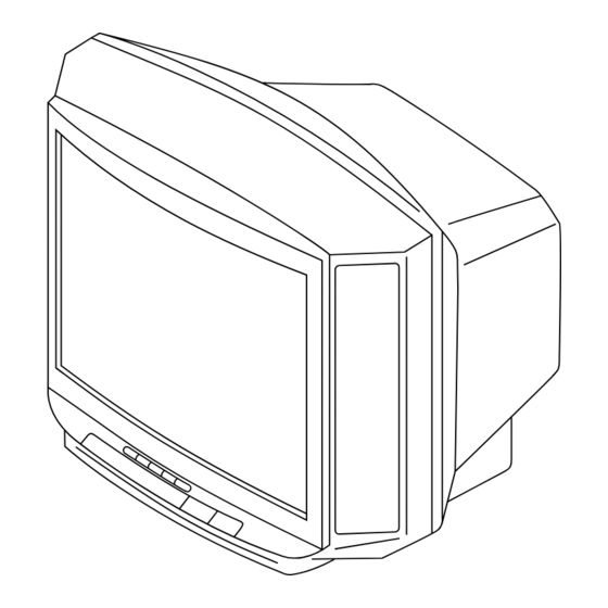
SECTION 1 The operating instructions mentioned here are partial abstracts from the Operating Instr uctions Manual. The page numbers of the Operating GENERAL Instruction Manual remain as in this manual. -
Page 8: Disassembly
SECTION 2 DISASSEMBLY 2-2. A BOARD REMOVAL 2-1. REAR COVER REMOVAL Remove the rear cover. Lever Lever Five screws (BVTP4×16) A board 2-3. SERVICE POSITION A board 2-4. REPLACEMENT OF PARTS For replacement of the Control Button, cut the welded portions from them, exchange with the new parts, and fix them with screws (+BVTP) respectively. -
Page 9: Demagnetization Coil And Picture Tube Removal
2-5. DEMAGNETIZATION COIL AND PICTURE TUBE REMOVAL Spring Demagnetization coil C board Deflection yoke A board Four screws (Tapping screws) Anode cap Picture tube Cushion • REMOVAL OF ANODE-CAP NOTE : Short circuit the anode of the picture tube and the anode cap to the metal chassis, CRT shield or carbon paint on the CRT, after removing the anode. -
Page 10: Set-Up Adjustments
SECTION 3 SET-UP ADJUSTMENTS • The following adjustments should be made when a complete Perform the adjustments in order as follows : realignment is required or a new picture tube is installed. 1. Beam Landing • These adjustments should be performed with rated power 2. -
Page 11: Convergence
If the V.STAT magnet is moved in the direction of the a and b 3-2. CONVERGENCE arrows, the red, green, and blue points move as shown below. Preparation : • Before starting this adjustment, adjust the focus, horizontal size, and vertical size. •... - Page 12 (2) Dynamic Convergence Adjustment Preparation : • Before starting this adjustment, adjust the horizontal static 3. Move the deflection yoke as shown in the figure below and optimize the convergence. convergence and the vertical static convergence. 4. Tighten the deflection yoke screws. 1.
-
Page 13: Focus Adjustment
DATA 3-3. FOCUS ADJUSTMENT Adjust FOCUS control on the C board (RV703) for the best focus. SERVICE Adjustment Item Item number WRITE MUTING Green FOCUS Executes the writing (NOT USED) SCREEN (NOT USED) FLYBACK TRANSFORMER (T851) 3-4. G2 (SCREEN) AND WHITE BALANCE Note: Screen VR is not used. -
Page 14: Self Diagnosis Function
SECTION 4 SELF DIAGNOSIS FUNCTION If no acknowledgement is returned from a device which is turned "ON", the device has a problem. In this case, one of the LED's responding to the problem device will flicker a defined number of times. Flickering is operated by lighting the LED's for 60ms each time. -
Page 15: Circuit Adjustments
SECTION 5 CIRCUIT ADJUSTMENTS 5-1. ADJUSTMENTS WITH COMMANDER Service adjustments are made with the RM-869 that comes with 1, 4 this unit. Raise/lower the service item number 3, 6 Raise/lower the data [MUTING] Writes Entering service mode Executes the writing With the unit on standby ↓... -
Page 16: Adjustment Method
5-2. ADJUSTMENT METHOD Item Number 08 Use the same method for Items Number 00-40. Use 1 and 4 to This explanation uses V-SHIFT as an example. select the adjustment item, use 3 and 6 to adjust, write with 1. Select 08 V-SHIFT with the 1 and 4 buttons. , then execute the write with -. - Page 17 Adjustment Item Table Item Initial Note for Different Data Standard Data Function Device Item Data 50/60Hz/RGB 50/RGB 60 1F/28/1F/28 H Shift 50/60Hz/RGB 50/RGB 60 20/20/20/20 H Size 50/60Hz 20/20 Pin Amplitude 50/60Hz 20/20 Corner Pin 50/60Hz 20/20 Tilt 50/60Hz 1F/1F V Slope 50/60Hz 2A/2A...
- Page 18 Item Initial Note for Different Data Standard Data Function Device Item Data OSD H Position D/K Stereo enable/disable Muting on/off at No Sync Bright ABL Switch SECAM Trap active/inactive FBT L/S C/M strict/plain Optional Flags 0 (see below) Optional Flags 1 (see below) Optional Flags 2 (see below) NOTE •...
- Page 19 Option Note 13. VPX bit 7 bit 6 bit 5 bit 4 bit 3 bit 2 bit 1 bit 0 Item – – – Initial data EHT Tracking Mode 1 = on V and E–W, 0 = only on V 0A (7) Enable Vertical Guard 1 = enable, 0 = disable...
-
Page 20: A Board Adjustment After Ic003 (Memory) Replacement
5-3. A BOARD ADJUSTMENT AFTER IC003 5-4. PICTURE DISTORTION ADJUSTMENT (MEMORY) REPLACEMENT Item Number 00 – 08 HSF (H SHIFT) 1. Enter to Service Mode. 2. Press commander buttons 5 and - (Data Initialize), and 2 and - (Data Copy) to initialize the data. HSZ (H SIZE) A BOARD (L807) 3. -
Page 21: Diagrams 6-1. Block Diagram
TUNER, IF, Y/C JUNGLE, SECAM DECODER, H/V OUT, MEMORY, SYSTEM CONTROLLER, AUDIO/VIDEO IN/OUT, POWER SUPPLY PRINTED WIRNING BOARD – A BOARD – A BOARD A BOARD WAVEFORMS A BOARD IC300 TDA8375A DIODE IC001 D–11 IC002 E–10 D001 D–9 – IC003 E–10 D002 C–12 –... -
Page 22: Schematic Diagram Of A Board
(1) Schematic Diagram of A Board J1201 J1202 CN103 :S-MICRO CN101 CN251 TO C BOARD J251 :S-MICRO :S-MICRO CN703 FB103 JW099 1.1UH 15MM AUDIO(L) AUDIO(R) D252 C111 C339 DA204K 1000p 150p R1211 R1205 R256 B:CHIP CH:CHIP IC203 R252 R1212 R1201 :CHIP :CHIP TA8248K... -
Page 23: Exploded Views
SECTION 7 EXPLODED VIEWS The components identified by ¡ shading and mark are criti- NOTE: • The construction parts of an assembled cal for safety. Replace only with part number part are indicated with a collation number • Items with no part number and no specified. -
Page 24: Circuit Boards Location
The components identified by SECTION 8 ¡ shading and mark are criti- cal for safety. ELECTRICAL PARTS LIST Replace only with part number specified. REF. NO. PART NO. DESCRIPTION REMARK REF. NO. PART NO. DESCRIPTION REMARK NOTE: ------------ ------------- ------------------- ------------- ------------ -------------... - Page 25 The components identified by ¡ shading and mark are criti- cal for safety. Replace only with part number specified. REF. NO. PART NO. DESCRIPTION REMARK REF. NO. PART NO. DESCRIPTION REMARK ------------ ------------- ------------------- ------------- ------------ ------------- ------------------- ------------- C310 1-164-004-11 CERAMIC CHIP 0.1MF C501 1-102-228-00 CERAMIC...
- Page 26 The components identified by ¡ shading and mark are criti- cal for safety. Replace only with part number specified. REF. NO. PART NO. DESCRIPTION REMARK REF. NO. PART NO. DESCRIPTION REMARK ------------ ------------- ------------------- ------------- ------------ ------------- ------------------- ------------- C1213 1-126-960-11 ELECT D551 8-719-908-03 DIODE GP08D...
- Page 27 Q418 8-729-424-67 TRANSISTOR UN2216 Q561 8-729-200-17 TRANSISTOR 2SA1091-O JR050 1-216-295-91 SHORT Q801 8-729-140-50 TRANSISTOR 2SC3209LK JR052 1-216-295-91 SHORT Q802 8-729-810-49 TRANSISTOR 2SD1877S-SONY-CA JR101 1-216-295-91 SHORT JR111 1-216-295-91 SHORT Q902 8-729-421-19 TRANSISTOR UN2213 JR112 8-719-041-97 DIODE MA113-(TX) Q903 8-729-421-19 TRANSISTOR UN2213...
- Page 28 The components identified by ¡ shading and mark are criti- cal for safety. Replace only with part number specified. REF. NO. PART NO. DESCRIPTION REMARK REF. NO. PART NO. DESCRIPTION REMARK ------------ ------------- ------------------- ------------- ------------ ------------- ------------------- ------------- R114 1-216-041-00 RES,CHIP 1/10W R407...
- Page 29 The components identified by ¡ shading and mark are criti- cal for safety. (a)(c) Replace only with part number specified. REF. NO. PART NO. DESCRIPTION REMARK REF. NO. PART NO. DESCRIPTION REMARK ------------ ------------- ------------------- ------------- ------------ ------------- ------------------- ------------- R805 1-216-081-00 RES,CHIP 1/10W...
- Page 30 *********************** R730 1-247-807-31 CARBON 1/4W 1-475-358-11 REMOTE COMMANDER (RM-869) R731 1-249-409-11 CARBON 1/4W 9-939-697-01 POCKET, COVER (FOR RM-869) R732 1-215-411-00 METAL 1/4W English Sony Ichinomiya Corporation 98BM08178-1 Printed in Japan 9-965-198-01 Quality Assurance Division © 1998. 2 – 42 –...
Need help?
Do you have a question about the TRINITRON KV-J14M1J and is the answer not in the manual?
Questions and answers