Advertisement
Quick Links
Advertisement

Summary of Contents for Nothern Industrial tools Plasma 275
- Page 1 32497...
-
Page 2: Specification
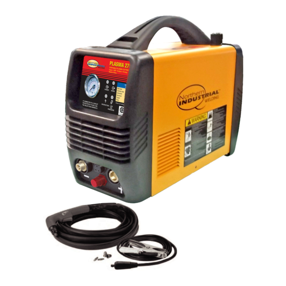
Please retain instructions for future reference. Plasma 275 Description The Plasma 275 is an IGBT inverter plasma cutter with thermal overload protection, a Trafimet torch and a built-in gas regulator. This easy to use plasma cutter has the power to cut up to 1/8 in. - Page 3 Plasma Cutter Plasma Cutter Operating Instructions and Parts Manual Plasma 275 Know your Welder Gas Pressure Handle Adjustor Cutting chart Connector for Gas Pressure Grounding Cable Display Connector for Cutting Torch Grounding Cable with Clamp Connector for Torch Arc Starting Cable...
- Page 4 Plasma Cutter Plasma Cutter Operating Instructions and Parts Manual Plasma 275 Low Gas Indicator Light This light will be on when the gas flow is low. Ground Cable Connection Connect the ground cable to the postive (+) receptacle on the front of the plasma cutter.
- Page 5 Plasma Cutter Plasma Cutter Operating Instructions and Parts Manual Plasma 275 -Always be aware of your work environment. Be sure to keep other people, especially children, away from you while you are cutting. -Keep harmful arc rays shielded from the view of others.
- Page 6 Plasma Cutter Plasma Cutter Operating Instructions and Parts Manual Plasma 275 -Insulate yourself from the work piece. Avoid contacting the work piece or ground. - Do not attempt to repair or maintain the plasma cutter while the power is on.
- Page 7 Plasma Cutter Plasma Cutter Operating Instructions and Parts Manual Plasma 275 -Do not operate any plasma cutter in areas where flammable or explosive materials are present. -Remove all flammable materials within 35 feet of the plasma cutting arc. If removal is not possible, tightly cover them with fireproof covers.
-
Page 8: Installation
Plasma Cutter Plasma Cutter Operating Instructions and Parts Manual Plasma 275 -Keep cylinders away from welding/cutting or electrical circuits. -Use the proper regulators, gas hose and fittings for the specific application Proper Care, Repair and Maintenance -Always have power disconnected when working on internal components. -
Page 9: Operation
Plasma Cutter Plasma Cutter Operating Instructions and Parts Manual Plasma 275 5. Connect the grounding cable to the positive (+) receptacle. 4. Line the electrode and nozzle and Gournding Clamp slide on. Quick Connector 6. Illustration of Complete 5. Install the cover to the torch and Assembly screw on. - Page 10 Plasma Cutter Plasma Cutter Operating Instructions and Parts Manual Plasma 275 60Hz, single phase, 20 amp power source. 1. Set up - Check the plasma cutter to see if it has been connected correctly and is in good working condition as...
- Page 11 Plasma Cutter Plasma Cutter Operating Instructions and Parts Manual Plasma 275 - The plasma cutter’s working air spare parts (e.g., torch, electrode, pressure range is 40-90psi. Notice: nozzle, ground clamp, etc.). the internal pressure switch will shut - Never allow a person with a cardiac...
- Page 12 Plasma Cutter Plasma Cutter Operating Instructions and Parts Manual Plasma 275 Trouble shooting Chart Symptom (s) Possible Causes(s) Corrective Action(s) Power Indicator 1.The light is broken. 1.Replace. Light is off after 2.Fuse is blown. 2.Replace. turning on the 3.Not 120V Input Voltage.
- Page 13 Plasma Cutter Plasma Cutter Operating Instructions and Parts Manual Plasma 275 supply. 2.Power supply switch is 3.Replace. 4.Replace. broken. 3.Fuse is damaged. 5.Examine and repair or 4.Transformer is broken. replace. 5.Main controlling board is ruined. Protection indicator 1.High/low voltage 1.The...
- Page 14 Plasma Cutter Plasma Cutter Operating Instructions and Parts Manual Plasma 275 Main Circuit...
- Page 15 Plasma Cutter Plasma Cutter Operating Instructions and Parts Manual Plasma 275 Description Specification Code Handle CUT40IIPH-2 2.05.08.019 Enclosure G20CUT40IIP.1 1.1.01.01.0226 Power cord 38*16*8(CUT40IIPH.3-8) 2.05.17.020 holder Main Switch R210-1C2N-BG1-WN 2.07.80.213 Gas valve G20CUT40 1.1.02.02.0414 connector Power cord EG-13.5(PG13.5) 2.04.30.102 holder Power cord plug 3*2.08mm2*2.5m...
- Page 16 Plasma Cutter Plasma Cutter Operating Instructions and Parts Manual Plasma 275 Gas connector II CUT30PH.3-3 1.1.02.02.0408 Gas valve board CUT40IIPH.3-4 1.1.02.01.1303 Gas valve G20CUT40IIP.3.11 1.2.07.02.0540 Middle board CUT40IIPH.3.1 1.1.02.01.1302 CUT40IIPU-1(CUT plastic panel 2.05.05.932 front/back) Rectifier MDQ5010 50A/1000V 2.07.37.501 G12038HA1SL AC110V 2.07.89.400...
- Page 17 Plasma Cutter Plasma Cutter Operating Instructions and Parts Manual Plasma 275 Power indicating CUT40IIPH.3.5 1.1.05.01.0013 board Bolt M3*15 2.06.01.701 Main P Handy CUT 16 1.1.05.01.0102 Control 1.2.07.02.0541 G20CUT40IIP.3.3 Transformer Pressure switch G20CUT40IIP.3.12 1.2.07.02.0539 Cutting Nozzle PC0116 S25-S45 2.20.04.901 Tip nozzle PD0116-0.8 S25-S45...
- Page 18 Plasma Cutter Plasma Cutter Operating Instructions and Parts Manual Plasma 275 Quincy, MA 02269-9101 Tel. (617) 770-3000 Fax (617) 770-0700 www.nfpa.org • OSHA Standard 29 CFR, Part 1910, Subpart Q. —WELDING, CUTTING AND BRAZING obtainable from your state OSHA office or from: U. S. Dept. of Labor OSHA, Office of Public Affairs Room N3647, 200 Constitution Ave.
Need help?
Do you have a question about the Plasma 275 and is the answer not in the manual?
Questions and answers