
Summary of Contents for Apex Digital PE 232 MKII
- Page 1 APEX PE Series Paragraphic Equalisers PE 232 MKII USER MANUAL APEX nv Schoebroekstraat, 62 3583 Beringen - Belgium Tel: +32 89 28 61 91...
-
Page 3: Table Of Contents
Contents Section 1 : Contents Section 2 : Introduction 2.1 The PE MKII series Section 3 : Performance Highlights Section 4 : Installation 4.1 Unpakking the unit 4.2 Checking the mains voltage 4.3 Setting the mains voltage 4.4 Replacing the mains fuse 5.5 The rear pannel 5.6 Rack mounting Section 5 : Signal connections... -
Page 5: Section 2 : Introduction
Introduction The PE MKII serie The APEX PE MKII series combines a graphic equaliser section with a parametric filter section. Wide-range Butterworth low and/or high pass filters precede the equalisers for added versatility and shaping of the response curve near the edges. The heart of each graphic equaliser section is a bank of 30 bandpass filters at distinct ISO centre frequencies or one filter for each 1/3 octave frequency. - Page 6 The controls of the graphic equaliser provides up to 12 dB of reciprocal cut and boost at the distinct ISO centre frequencies. The filters of the PE series preserve optimal filter bandwidth whatever the settings of the controls are. Because of this `constant Q’ circuitry, filter response does not broaden at low cut or boost settings.
- Page 7 All filter and equaliser functions of the PE232MKII are switchable IN and OUT of the signal paths. The complete unit can be bypassed by switching it off. The fail safe relays will react as if there were a mains failure and will link the input of each channel to its corresponding output.
-
Page 9: Section 3 : Performance Highlights
Performance Highlights PE232MKII • 2 x 30 band constant Q precision DLT graphic equaliser. • 2 x 2 band constant Q parametric equaliser/notch filter. • Variable HP filter. • Graphic equaliser in-out switchable. • Switchable scale 6/12 dB on graphic equalisers. •... -
Page 11: Section 4 : Installation
Installation In addition to these operating instructions and the PE MKII equaliser, the packaging also contains : • A power cord (see note for U.K.). NOTE This apparatus must be earthed. The wires of the mains lead are coloured in accordance with the following code : Green and yellow : Earth Blue : Neutral Brown : Live... -
Page 12: Checking The Mains Voltage
Checking • Check if the voltage selector on the rear of the equaliser indicates the correct supply voltage before connecting the the mains voltage equaliser to the mains. Setting • Remove the plug from the wall socket and check if the mains fuse is of the correct rating. -
Page 13: The Rear Panel
The rear panel 1 MAINS FUSE Holds the mains fuse. 2 MAINS SOCKET • Insert the plug of the mains lead into the mains socket. The mains connector is a standard 3 pin IEC connector. The centre terminal of the connector is directly connected to the chassis of the equaliser. -
Page 14: Rack Mounting
4 SERIAL NUMBER This number is the fingerprint of the unit and should be quoted in any correspondence concerning the unit. 5 SIGNAL GROUND LIFT This switch disconnects the signal ground from the mains and chassis earth. The switch should be used if hum due to ground loops is experienced and will generally solve the problem. -
Page 15: Section 5 : Signal Connections
Signal connections For maximum performance, the use of two-conductor shielded cable is recommend. Because the shield does not carry signal, interference between signal current and shield current is minimised in this way. Ordinarily the shield is connected to ground at one end Input The inputs of the equaliser are electronically balanced. -
Page 16: Output
Some general rules for input connections : • Although not necessary, because of input circuit symmetry, it is best to always use the “+” and “-” input terminals when wiring the equaliser. In this way, hum pick-up from the open terminal is avoided. -
Page 17: Grounding
Grounding Because it is not always possible to determine whether the equipment connected to the equaliser have their circuit ground connected to earth and because the mains earth is not always of good quality, it is hardly possible to give general rules for •... - Page 18 Figure A Figure B Figure C Figure D...
-
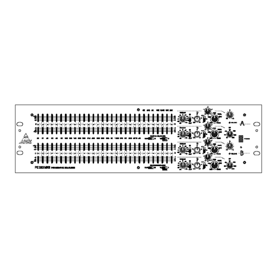
Page 19: Section 6 : The Equaliser
The Equaliser See fold out at the end of the manual When pressing the power button, AC mains is applied to the POWER unit. The red led below the power switch illuminates as you switch on the apparatus. The fail safe relays will open, switching the filters between the input and the output of the unit. - Page 20 The GAIN controls of the parametric/notch filters adjust the GAIN centre frequency gain of the corresponding parametric filter. The Q controls adjust the Q of each band. Setting Q to maximum result in a narrow band operation while a minimum Q result in a broadband operation.
- Page 21 The SCALE switch switches the range of the corresponding SCALE graphic equaliser section to 6dB or 12dB full scale. NOTE Note :The rotary controls of the PM232MKII are high quality conductive plastic potentiometers. However, calibration accuracy of these controls is only modest. Indications on the front panel therefore are principally intended...
-
Page 23: Section 7 : General Operating Instructions
General operating instructions Introduction If you are not familiar with equalisers, the best thing to do before first turn-on is to put all controls in their central position. When the unit is not powered or the power supply fails, the fail-safe relay of the equaliser links input and output. -
Page 24: Hp And Lp Filters
HP filter The HP filter has a continuously variable turnover frequency from 15 to 300Hz. The filter has a roll-off slope of 12dB/octave and is of the Butterworth type for maximally flat response. It is particularly useful in situations where potentially harmful subsonic signals are likely to cause speaker or amplifier overload. - Page 25 Boost a filter and discover the contrast between the subtle shelving effects available from broadband operation ( Q minimum ) and the ringing, coloured sound you get from narrowband peaking ( Q maximum ). Be careful when boosting frequencies outside the hearing range.
-
Page 26: Graphic Equaliser
that even at lower Q these non reciprocal filters remain essentially inaudible. In the overlapping regions, between two filter sections, you can adjust two adjacent sections to the same frequency. Because of the perfect combining response of the filters, responses are added. This is another way for building a deep, less sensitive notch. -
Page 27: Specific Applications
Specific This part of the manual describes very specific suggestions on applications how to use the PE232 in different applications. We recommend that you read these. The information contained in each may inspire you for setting-up your system. The proposed equaliser settings are only indicative and are no guarantee for successful implementation in your system. - Page 28 system response and to compensate for deficiencies in the room acoustics. Conference equalisation Low frequencies are attenuated for decreasing the effect of windhowl in the microphone, using the high pass filter with a 30 Hz cutoff. Hum is easily suppressed with a parametric filter in the notch mode.
-
Page 29: Section 8 : Specifications
Specifications INPUT: • Electronically balanced • Absolute overload point : +22dBu • Impedance: 10 Kž (each leg) equal impedance for “+” and “-” legs • CMRR better than 65dB (20Hz-20KHz) • XLR-3 type connector connections : 1 signal ground; 2 hot (+); 3 cold (-) OUTPUT: •... - Page 30 any point in the equaliser comes within 2dB of clipping FILTERS: Graphic equaliser: • 30 ISO centre frequencies: 25Hz-20KHz 1/3 octave • Centre frequency tolerance: ±1% (typically better than ±0.5%) • Q tolerance: ±1% • Max boost/cut: 6 or 12dB ±0.5dB reciprocal •...
-
Page 31: Section 9 : Maintenance And Service Information
Maintenance and service information Preventive Preventive maintenance consists of cleaning and visual inspecting the unit. When accomplished regularly, preventive maintenance maintenance may prevent malfunction and lengthen the apparatus life. The severity of the environment in which the equaliser is used determines the required frequency of preventive maintenance. - Page 32 SERVICE REQUEST FORM Please copy and complete this form as completely as possible and return it to Apex or an authorised Apex service centre together with the defective unit. Name/Company:............................Adress:................................................... Telephone:........Country:..............Model No:......... Serial No:.............. Purchased from:....... Date:..............•...
- Page 33 WARRANTY Summary We, APEX nv Bosdel 52 3600 GENK Belgium warrant to you, the original purchaser and any subsequent owner of this Apex product, for a period of one year from the date of purchase by the original purchaser that the product is free of defects in components and factory workmanship under normal use and service.
- Page 34 from us. Corrective action will be taken within a reasonable time of the date of receipt of the defective product by us or the service centre. If the repairs made by Apex or the authorised service centre are not satisfactory, notify Apex or the service centre immediately. Repairs Product changes We reserve the right to change the design on any product without prior notice and with no obligation to make corresponding changes...
Need help?
Do you have a question about the PE 232 MKII and is the answer not in the manual?
Questions and answers