Table of Contents
Advertisement
Quick Links
Advertisement
Table of Contents

Related Manuals for RF Code M250 Reader

Summary of Contents for RF Code M250 Reader
- Page 1 M250 Reader User Manual...
-
Page 3: Table Of Contents
Users Up-Connect Time Serial Ports Resetting The Reader Mounting Warranty & Service Limited Standard Warranty Terms Standard Warranty Limitations Obtaining Service & Support RF Code Customer Support Appendix Using the M250 Reader with Windows 7 PN01449 REV02 M250 Reader User Manual ... -
Page 4: Copyright Statement
The information in these pages is furnished for infor- mational use only, is subject to change without notice, and should not be construed as a commitment by RF Code, Inc. -
Page 5: Fcc Compliance
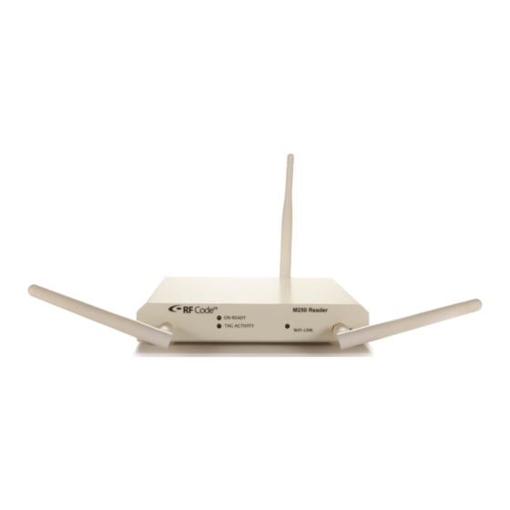
Operation of this equipment in a residential area is likely to cause harmful interference, in which case the user will be required to correct the interference at his own expense. RF Code is not responsible for any radio or television interference caused by using other than recommended cables and connectors or by unauthorized changes or modifications to this equipment. Unauthorized changes or modifica- tions could void the user’s authority to operate the equipment. - Page 6 The M250 reader is compatible with wired and wireless networks for rapid integration into an organization’s IT infrastructure. With a modular design and low price, the M250 Reader provides an economical solution to a wide variety of asset tracking problems. RF Code’s patented communication protocols allow for very high tag densities.
-
Page 7: Pn01449 Rev02
00/10 – When on, this LED indicates a 100MBit Ethernet connection. When off, this LED indicates a 10MBit Ethernet connection. • In Use – This LED indicates there is a connection to the M250 Reader and tag data is being read from the reader. • Status – This LED indicates that the M250 Reader is connected and receiving power. -
Page 8: Pn01449 Rev02
Environmental Conditions The M250 Reader is approved for use within the temperature ranges set forth below. • Operation: -20 to +70 degrees Celsius. • Storage: -40 to +80 degrees Celsius. Upgrading Reader Firmware The M250 Reader has the ability to be updated as new firmware is released. To upgrade the firmware, launch the Reader Configuration Utility, found on the RF Code Reader Utilities CD. For information regarding this process, please refer to the Reader Configuration Utility User Manual also located on the CD. Firmware can also be upgraded by downloading the latest version at the following support site: http://www.rfcode.com/support_downloads... -
Page 9: Pn01449 Rev02
Each antenna post supplies an RF signal to the two parallel radio receivers in the M250 Reader. Antenna input im- pedance is 50 ohms nominal. B oth the type of antennas used and the Reader range setting determine the effective read range. The normal Reader- range features are defined using ¼-wave helical antennas. These antennas are appropriate for most Reader applica- tions. Optional antennas that offer diverse receiving properties or extend the range of the Reader are available for the M250 Reader. -
Page 10: Pn01449 Rev02
COM ports listed. Select the COM port and click Next. You may change any setting in the configuration tabs including the IP address and Up-Connect settings. You must click Save Changes so that the configuration is saved to the reader. 5. Once a static IP is entered you should be able to connect to the M250 Reader with a web browser. If you wish to use DHCP, the Reader Configuration Utility will also report the IP address that has been assigned to the reader. However, this address may change, so it is recommended that you utilize the Up-Connect feature to connect the M250 Reader to the RFID software application. -
Page 11: Diagnostics
A ll RF Code tags are defined as being members of a specific group, and have a unique tag ID number within that group. The group code is a string of 6 letters and is assigned by RF Code. Each group code is unique for a given tag type. When an RF Code reader is configured, it can be supplied with up to 16 group codes. Each group code has a corresponding treatment code. The treatment code instructs the application software how to interpret the payload data for each tag event within that group code. - Page 12 Figure 4: Group ID, Tag ID, and Treatment Code Location Group Code Tag ID Treatment Code Figure 5: Example Tag Data in Tags Sub-Task PN01449 REV02...
-
Page 13: Summary
Summary The Summary sub-task can be accessed by navigating to Diagnostics > Summary. This sub-task is available to provide a report of version, model, IP address, etc. information that has been configured for the Reader. Figure 6: Summary Sub-Task There is also an option to reboot the Reader from the Summary screen. This can be done by selecting the Reboot button. You will be prompted with a dialog box to confirm if you want to reboot the reader. If you would like to reboot the reader, select the Reboot button. If you want to opt out, select the Don’t Reboot button. Tools The Tools sub-task can be accessed by navigating to Diagnostics > Tools. This sub-task is available to test reader connection with a server or to reboot the reader. -
Page 14: Configuration
Configuration Within the Configuration task, there are five sub-tasks that will allow you to modify settings that were initially config- ured using the Reader Configuration Utility: Network Configuration, Reader Configuration, Users, Up-Connect, and Time. Network Configurations The Network Configuration sub-task can be accessed by navigating to Configuration > Network Configuration. Within this sub-task you may view and modify the different types of network configurations you have set up for the Reader. Please refer to the Reader Configuration Utility Manual for more information regarding specific network configuration tasks. SSL Certificate Configuration By default, when HTTPS is enabled, a self-signed 10-year SSL certificate is generated so that communication on HTTPS port is encrypted. To communicate with both encryption and authentication, an SSL certificate must be digitally signed by a well-known certificate authority (CA). Please contact your Network or System Administrator for obtaining a signed SSL Certificate. To configure the M250 Reader with the SSL Certificate perform the following steps: 1. O btain a private key using a preferred tool or a certificate authority may provide this service. Please archive the key and file in a safe place for security purposes. This key will be needed for SSL certificate configuration later. 2. A Certificate Signing Request (CSR) is generated based on the private key. 3. Submit the CSR to a certificate authority. 4. The certificate authority issues an SSL certificate based on the CSR and in a PEM format. 5. Once a signed SSL certificate is obtained from CA, import it to the M250 Reader: 6. C opy the SSL certificate portion from “BEGIN CERTIFICATE” to “END CERTIFICATE” from the PEM and paste it into the “SSL Certificate” field. -
Page 15: Reader Configuration
Figure 8: Network Configuration Sub-Task To ensure that any modified settings are implemented, click the Save Changes button. Reader Configuration The Reader Configuration sub-task can be accessed by navigating to Configuration > Reader Configuration. Within this sub-task you may view and adjust the Noise Floor level for Channel A and Channel B of the Reader. Figure 9: Reader Configuration Sub-Task • Channel A Dynamic Noise Floor - When this box is checked, the noise floor for this channel is adjusted automatically. • Channel A Noise Floor - Enter a value to set the noise floor for channel A antenna. • Channel B Dynamic Noise Floor - When this box is checked, the noise floor for this channel is adjusted automatically. •... -
Page 16: Users
Users The Users sub-task can be accessed by navigating to Configuration > Users. This sub-task can be used to add user authentication to the M250 Reader. Figure 10: Users Sub-Task Add a User • To add a user, click the New button. • E nter a username, password, confirm the password and select a user role. • Administrator - has complete access and control of the Configuration and Diagnostic task • C onfiguration View - has view only access to the Configuration task and can utilize the Diagnostics tasks • Event View - only has access to the Diagnostics tasks of the Reader • Click the Save Changes button. -
Page 17: Up-Connect
Up-Connect The Up-Connect sub-task can be accessed by navigating to Configuration > Up Connect. This sub-task allows for reader communication with Zone Managers to be more “firewall friendly”. When this option is selected, the M250 Reader is configured to initiate the contact with the Zone Manager rather than requiring that access be granted to allow the Zone Manager to connect to readers behind a firewall. Figure 11: Up Connect Sub-Task Configuring Up-Connect To add an Up-Connect Configuration, click the New button. Populate the following fields and click the Save Changes button. • ID - Enter a name for the Up Connect configuration. • Enabled - Check this box to enable the reader to up connect to a Zone Manager. • Hostname - Input the IP address of the Zone Manager that the reader should connect to. • Port - Input the port number over which the reader will communicate with the Zone Manager. • Up Connect ID/Password - Input and verify a reader ID and password that will be utilized in the Up Con- nect configuration of Zone Manager. • Status - Once the Up Connect link has been configured, this field will populate with the connections status for the Up Connect link. User configuration is not require for this field. • Message - This field will populate with a message regarding the status of the Up Connect link. User configura- tion is not required for this field. Deleting an Up-Connect Configuration To delete an Up-Connect Configuration, select the configuration from the list that you wish to delete and click the Delete button. -
Page 18: Time
Time The Time sub-task can be accessed by navigating to Configuration > Time. This sub-task allows the time settings to be configured for a Reader. By default this Reader function is already set to local time with access configured for three NTP (Network Time Protocol) Servers. Users may need to adjust these settings for their own network security policies. There are three primary ways that users may desire to configure their time settings: Figure 12: Time Sub-Task 1. Default - In this instance, the time would be automatically set using the NTP Server and then would continue to automatically keep time by periodically checking with the three default NTP Servers provided from the factory. 2. Automatic Time Configuration - In this instance, the time can be manually set by choosing a date and time from the pull-down menu and clicking the Set to your computer’s time button. Then the NTP Server that are configured by default can be edited, deleted, or moved by clicking on the corresponding button. Finally, click upon the Save Changes button to save the configuration. -
Page 19: Serial Ports
Serial Ports The Serial Ports sub-task can be accessed by navigating to Configuration > Serial Ports. This sub-task allows for the configuration of the Reader for USB Serial Device integration (such as a Global Positioning System device). Figure 13: Serial Ports Sub-Task To access this sub-task a USB serial device must be plugged-in to the Reader. Once you have plugged the device into the Reader, access the Serial Ports sub-task by navigating to Configuration > Serial Ports. The serial device will appear in the list on the left and you will notice that the Serial Port configuration menu (on the right) is populated by default based on settings obtained from the serial device. Some configuration may be necessary for your serial device. The configuration (if any) that is needed will be determined by consulting the device literature (user manual, etc.) that came with your serial device. PN01449 REV02... - Page 20 Resetting The Reader To reset the Reader settings back to the factory defaults, follow these steps: 1. V erify that power is applied to the reader. Make sure you can tacitly feel, the button being depressed. For example, most ball-point pens are not long enough to engage the button. 2. Flip the Reader upside-down. 3. Using a pointed object, press the Reset button for a few seconds. 4. Release the Reset button. 5. The Reader will now be reset to the factory default settings. Figure 14: Reader Reset Button Illustration BOTTOM SIDE OF READER Serial Number Reset Button...
- Page 21 Mounting To Mount the Reader please use the following steps: 1. F lip the Reader upside-down and use the 4 screws provided to attach the mounting plate to the bottom of the Reader. 2. Attach the RF antennas and the WiFi antenna (for optional Wi-Fi enabled M250 Readers). 3. U sing screws (not-provided) thread them through the mounting cut-outs on the mounting bracket and mount the Reader to the wall or ceiling. 4. Attach the provided Power supply cord to the Reader and to an available electrical outlet or use the PoE (Power over Ethernet) feature to power the reader. All M250 Readers support and have built-in PoE and also do not require an external adapter. Figure 15: Reader Mounting Plate Illustration Attach to Reader Mounting Cut-outs...
-
Page 22: Warranty And Service
Standard Warranty Limitations Except as provided herein, the entire liability of RF Code and its suppliers under this limited warranty will be that RF Code will use reasonable efforts to repair or replace, without charge, all defective Products returned to RF Code by a Customer, as more particularly described in the End User Warranty. -
Page 23: Using The M250 Reader With Windows
Appendix Using the M250 Reader with Windows 7 To use the M250 Reader with the Windows 7 Operating System the following additional configuring steps should be performed: 1. Install the M250 Reader driver software that came with your RF Code Reader Configuration Utility CD. Figure 16: M250 Reader Driver Software Installation 2. Navigate to Start > All Programs > Devices and Printers. PN01449 REV02 M250 Reader User Manual ... - Page 24 Figure 17: Navigate to Devices and Printers 3. R ight-click on the RF Code M250 Reader and select Properties. Figure 18: Select M250 Reader Properties PN01449 REV02...
- Page 25 4. Access the Hardware tab and select Properties. Figure 19: Select Properties in the Hardware Tab 5. Click Change Settings and Update Driver. Figure 20: Update Driver Option PN01449 REV02...
- Page 26 6. Choose Browse my computer for driver software. Figure 21: Browse My Computer Option 7. Select the folder in which you have installed the Reader Configuration Utility. Figure 22: Folder Selection PN01449 REV02...
- Page 27 Install this driver software anyway. Figure 23: Install Driver Software 9. You will see a dialog box indicating that the driver software has been installed successfully. You can now ac- cess your M250 Reader using the M250 Reader Web-Console. Figure 24: M250 Reader Driver Installed Successfully 10. PN01449 REV02...
Need help?
Do you have a question about the M250 Reader and is the answer not in the manual?
Questions and answers