Table of Contents
Advertisement
4033352 /5
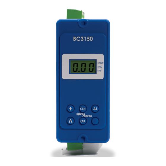
BC3150
Blowdown Controller
Installation and Maintenance Instructions
BC3150
x1000
x100
x10
AL
CLN
OK
IM-P402-130 AB Issue 7
Printed in the UK
IM-P403-88
AB Issue 5
1. Safety information
2. User instructions and
delivery information
3. System overview
4. Mechanical installation
5. Electrical installation
6. Commissioning
- Quick set-up
- Full
7. Communications
8. Maintenance
9. Fault finding
10. Technical information
- Default settings
11. Appendix
- Data registers
12. Menu map
© Copyright 2013
Printed in GB
Commissioning password
Current legislation states that in order to prevent tampering and potentially
hazardous programming errors, access to the pass codes required to enter
commissioning mode should only be available to qualified and trained
personnel.
Enter commissioning
To enter the commissioning mode, press and hold the
The display will show the pass code '888'. Enter the pass code '745'. This is fixed
and cannot be changed.
If the wrong passcode is entered, the display will return to showing the current
process variable - run mode.
Special features
CALIBRATION from the Run Menu
Enables the operator (e.g. water treatment engineer / specialist) to calibrate the
controller from the run menu. A pass code is not required.
-
Using the
button, select 'CAL'.
-
Pressing
button will access the calibration menu in commission mode. See
OK
Section 6.3.10 CAL- calibration.
-
On completion or exiting calibration, the display will return to the process
variable run menu and normal control will be resumed.
This page MUST be removed after
commissioning
and kept in a safe,
access controlled location.
button for 5 seconds.
OK
IM-P402-88 AB Issue 5
Advertisement
Table of Contents

Subscribe to Our Youtube Channel
Summary of Contents for Spirax Sarco BC3150
- Page 1 IM-P403-88 AB Issue 5 Current legislation states that in order to prevent tampering and potentially hazardous programming errors, access to the pass codes required to enter BC3150 commissioning mode should only be available to qualified and trained personnel. Blowdown Controller...
- Page 2 IM-P402-88 AB Issue 5 IM-P402-88 AB Issue 5...
-
Page 3: Safety Information
This product is suitable for Class A Environments (e.g. industrial). A fully detailed EMC assessment has been made and has the reference number UK Supply BH BC3150 2008. The product may be exposed to interference above the limits of Heavy Industrial Immunity if: The product or its wiring is located near a radio transmitter. - Page 4 Symbols Equipment protected throughout by double insulation or reinforced insulation. Functional earth (ground) terminal, to enable the product to function correctly. Not used to provide electrical safety. Clean earth / ground. Safety earth. Caution, risk of electric shock. Caution, risk of danger, refer to accompanying documentation. Optically isolated current source or sink.
-
Page 5: Intended Use
Determine the correct installation situation and direction of fluid flow. iv) Spirax Sarco products are not intended to withstand external stresses that may be induced by any system to which they are fitted. It is the responsibility of the installer to consider these stresses and take adequate precautions to minimise them. -
Page 6: Protective Clothing
1.16 Returning products Customers and stockists are reminded that under EC Health, Safety and Environment Law, when returning products to Spirax Sarco they must provide information on any hazards and the precautions to be taken due to contamination residues or mechanical damage which may present a health, safety or environmental risk. -
Page 7: All Rights Reserved
Spirax-Sarco Limited. 2.1 General description The BC3150 is a blowdown controller for steam boilers. It controls TDS (total dissolved solids – salts in solution) by opening and closing a blowdown valve. -
Page 8: Alarm Button
2.4 Manual test buttons (in priority order) Note: When these buttons are released, the product will return to 'PV' or 'end' depending if pressed in run or commissioning mode. Alarm button This button can be used to test the alarm relay and the external circuits. The product will display, 'AL' + 'tSt' (meaning test) + 'PV' (TDS of conductivity) Note: The Alarm only occurs whilst the key is pressed. -
Page 9: Lcd Display
2.6 LCD display After initially applying power to the product, it will automatically enter run mode. The current conductivity or TDS will then be displayed or 000 if a purge time has been set or the product has not been calibrated. In normal operation (run mode) the display shows the actual Total Dissolved Solids (TDS) value in µS/cm or ppm, depending on the option chosen. - Page 10 2.7 Information line details (in priority order): Alarm: Indicates the alarm relay has been de-energised/released. The operator is testing the alarm relay. The PV value has exceeded the alarm level. Probe cleaning / conditioning The operator has started a cleaning cycle. TDS blowdown valve (Total Dissolved Solids): Indicates the blowdown relay is energised.
-
Page 11: Receipt Of Shipment
Each carton should be unpacked carefully and its contents checked for damage. If it is found that some items have been damaged or are missing, notify Spirax Sarco immediately and provide full details. In addition, damage must be reported to the carrier with a request for their on-site inspection of the damaged item and its shipping carton. -
Page 12: System Overview
The product can accept a signal from a Spirax Sarco conductivity probe (CP10 or CP30) and a Pt100 temperature sensor. A CP32 probe may also be used with the BC3150, but will not provide the scale monitoring and self-cleaning features. -
Page 13: Other Features
3.4 Other features To prevent unwanted or inadvertent changes being made, most commissioning parameters are protected with a pass code. The BC3150 can communicate via an infrared link between adjacent controllers – see Section 7, Communications. IM-P403-88 AB Issue 5... - Page 14 3.5 Typical applications - Boiler control systems (BCS) BC3150 x1000 x100 Fig. 5 BCS1 system BC3150 x1000 x100 Fig. 6 BCS2 system IM-P403-88 AB Issue 5...
- Page 15 BC3150 x1000 x100 Fig. 7 BCS3 system BC3150 x1000 x100 Fig. 8 BCS4 system IM-P403-88 AB Issue 5...
-
Page 16: System Description
The 500 mm head prevents flash steam flow in the bypass line. We recommend a 3-port diverter valve such as the Spirax Sarco QL. A spring retract pneumatic actuator is normally fitted to cause the valve to divert on failure of the air supply. - Page 17 Spring retract pneumatic actuator 3-port diverter valve Check valve Bypass line 500 mm BC3150 head Conductivity sensor temperature sensor Fig. 9 Typical application - CCD system Isolating valve (spring-to-close) opens to allow clean condensate to be returned to the boiler.
-
Page 18: Mechanical Installation
4. Mechanical installation Note: Read the 'Safety information' in Section 1 before installing the product. The product must be installed in a suitable industrial control panel or fireproof enclosure to provide impact and environmental protection. A minimum of IP54 (EN 60529) is required. - Page 19 Cut the panel to the dimensions given in Figure 11. Drill the screw holes in the panel in the positions indicated. Remove the backing from the gasket supplied and apply to front face of the product. The bezel can be used to enhance the appearance of the panel cutout. If required, fit this to the outside of the panel.
-
Page 20: Electrical Installation
Use only the connectors supplied with the product, or spares obtained from Spirax Sarco Limited. Use of different connectors may compromise product safety and approvals. Ensure there is no condensation within the unit before installing and connecting the power. - Page 21 12. Additional protection must be provided to prevent accessible parts (e.g. signal circuits) from becoming Hazardous Live if a wire or screw is accidentally loosened or freed. Ensure all wires are secured to at least one other wire from the same circuit. The attachment must be as close to the terminal block as possible but must not apply undue stress on the connection.
- Page 22 5.2 Mains wiring notes: Read Section 5.1 before attempting to wire the supply to the product. The wiring connections are identified on the terminal plugs. Fuses should be fitted in all live conductors. Disconnect device conforming to IEC 60947-1 and IEC 60947-3 Product 3 A fuse Fig.
- Page 23 Note: The protective earth must be connected in accordance with National or Local regulations. LINK LINK 230 /115 Vac (BCV30 3 4 5 3 4 5 N Y1 Y2 22 Blowdown valve Solenoid valve See Section 5.2 (BCV1, BCV20, or BCV31) Mains wiring notes Alarm Input...
-
Page 24: Probe Wiring
5.3 Signal wiring notes An earth current loop is created if a wire or screen is connected between two earth points that are at different potential (voltage). If the wiring diagram is followed correctly, the screen will only be connected to the earth at one end. The earth terminal is a functional earth rather than a protective earth. - Page 25 5.5 Probe in blowdown (or condensate) line - CP10 For most applications the 1.25 m (4 ft) heat resisting probe cable will need to be extended using a junction box. If not, link terminals 50 to 51, and 52 to 53. Note: Whilst pairs of conductors are linked at the junction box, the four wire connection is required to compensate for voltage drop.
-
Page 26: General Information
If during commissioning, the buttons are not pressed for over 5 minutes, the controller will revert to run mode and an error will be displayed. If the commissioning was incomplete the controller may not provide the correct control. BC3150 x1000 LCD display... - Page 27 6.2 Commissioning - Quick set-up This section allows the user to carry out the minimum commissioning necessary to operate the system. It accepts the defaults set in the factory, so will only work if the original default settings have not been altered. See default settings in Section 10, Technical information, to confirm. Settings can then be tailored to suit the individual requirements of the customer / application if required.
-
Page 28: Main Structure
6.3 Commissioning - Full 6.3.1 Main structure On entering the correct pass code, the display will show the following menu structure:- rAnge multiplier setting (x10, x100, x1000). Blank = x1. Selects conductivity units: ON = μS/cm (default) OFF = ppm Set Point. - Page 29 0 or 4 mA. Sets output to 0 - 20 mA or 4 - 20 mA. Internal temperature compensation. Sets a default water temperature if a Pt100 is not fitted. Probe Factor. Displays a figure that indicates the probe condition. End –...
- Page 30 6.3.3 µS/cm – Units Micro Siemens/cm is the preferred option. Press the button to select On for µS/cm. Press the button to select OFF, for ppm. Press the button to confirm your selection and move to the next menu option. 6.3.4 SP - Set Point The set point is the TDS value at which the blowdown or dump valve will open.
- Page 31 6.3.8 bur – Burner input This feature is not visible if the Purge is set to zero (i.e. sensor in boiler). The interval time between purges is fixed to ½ hour. This can be set to be independent of burner firing (off), or dependant on cumulative boiler firing time (on). button to select On for dependant.
- Page 32 (the set point). 5 litres (1.3 US gallons) will be plenty for most systems. Use the Spirax Sarco MS1 conductivity meter to check the conductivity. Close both stop valves (Figure 9, page 17) and open the drain valve and 'water for flushing and calibration' valve.
-
Page 33: Infrared (Ir)
6.3.14 PF – Probe factor Shows the calculated probe factor, which indicates the condition of the probe. This function cannot be edited. See Section 9, fault finding, for acceptable limits. 6.3.15 End Press the button to enter run mode. 7. Communications 7.1 Infrared (IR) All products in the range can communicate via an infrared link between adjacent controllers. -
Page 34: Maintenance
8. Maintenance Note: Read the 'Safety information' in Section 1 before carrying out any maintenance. No special servicing, preventative maintenance or inspection of the product is required. During installation or maintenance, the rear of the product must be protected from environmental pollutants entering the product. -
Page 35: Fault Finding
9. Fault finding WARNING: Before fault finding read the Safety information in Section 1 and the General wiring notes in Section 5.1. Please note that there are hazardous voltages present and only suitably qualified personnel should carry out fault finding. The product must be isolated from the mains supply before touching any of the wiring terminals. -
Page 36: System Faults
9.2 System faults Symptom Action 1. Switch off the mains supply to the product. 2. Check all wiring is correct. 3. Check external fuse(s) are intact. Replace if necessary. 4. Check the mains voltage is within specification. 5. Switch on mains supply. If symptoms are still present return the product for examination. - Page 37 Symptom Action 1. Monitor the mains supply and ensure it is continuous and within the specification limits. 2. Measure the ambient temperature and ensure it is less than specified. Product 3. Investigate symptom 2. powers up for Explanation a period of A re-settable thermal cut-out device will operate if one or more time (greater of the following occurs:...
-
Page 38: Operational Error Messages
A high TDS alarm The feedwater quality and treatment has occurred. regime should be checked as soon as Alarm 1 possible. Spirax Sarco offer boiler water treatment advice and service. Some errors latch the alarm relay for 1. Enter the commissioning (setup) mode. -
Page 39: For Technical Assistance
10. Technical information 10.1 For technical assistance Contact your local Spirax Sarco representative. Details can be found on order / delivery documentation or on our web site: www.spiraxsarco.com 10.2 Returning faulty equipment Please return all items to your local Spirax Sarco representative. Please ensure all items are suitably packed for transit (preferably in the original cartons). - Page 40 10.5 Cable / wire and Connector data Mains and signal connector Rising clamp plug-in terminal blocks with screwed Termination connectors Cable size 0.2 mm² (24 AWG) to 2.5 mm² (14 AWG) Stripping length 5 - 6 mm Note: Use only the connectors supplied by Spirax-Sarco Limited – Otherwise Safety and Approvals may be compromised.
-
Page 41: Water Conductivity
10.6 Input technical data Water conductivity Probe types: CP10, CP30 and CP32 Minimum ≥ 1 µS @ 25°C 0 - 9.99 ppm or μS / cm Ranges 0 - 99.9 ppm or μS / cm 0 - 999 ppm or μS / cm 0 - 9990 ppm or μS / cm ±2.5% FSD (possibly >... - Page 42 Relay(s) Contacts 2 x single pole changeover relays (SPCO) Voltage ratings (maximum) 250 Vac Resistive load 3 amp @ 250 Vac Inductive load 1 amp @ 250 Vac ¼ HP (2.9 amp) @ 250 Vac ac motor load HP (3 amp) @ 120 Vac Pilot duty load C300 (2.5 amp) - control circuit / coils Electrical life (operations)
- Page 43 Burner (bur) - Only available if PURGE time is greater than 0 seconds. Ranges ON or OFF Default Filter (FLt) - Only available if PURGE time is = 0 seconds. ON or OFF (TC = 64 or 8 seconds). Please note that the 8 second Ranges filter, also includes a 5% (FSD) Jump out function for CCD systems.
- Page 44 12. Menu map Normal run mode display X 1000 OK (5S) X 100 ENTER PASS CODE X 10 X 1 (= BLANK) 0 (mA) ON = μS /cm OFF = ppm 4 (mA) IM-P403-88 AB Issue 5...
Need help?
Do you have a question about the BC3150 and is the answer not in the manual?
Questions and answers