Table of Contents

Related Manuals for Kodiak KM10124

Summary of Contents for Kodiak KM10124
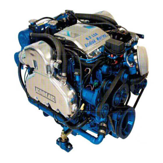
- Page 1 KODIAK MARINE SUPERCHARGED 6.2L LSA WARNING—DANGER OF DEATH OR PERSONAL INJURY BY KEM EQUIPMENT INC. KEM EQUIPMENT INC 10800 SW HERMAN RD. TUALATIN, OR. 97062 PH# (503) 692-5012 FAX# (503) 692-1098 KM10124 www.kemequipment.com REV-G 8/27/13...
- Page 3 We at KEM Equipment Inc. would like to congratulate you on your decision to recommend the Supercharged LSA Marine engine to your valued customer. The Kodiak 6.2L LSA Supercharged Marine fuel system, once properly set up, will give your customer many years of trouble free service.
- Page 4 Plumbing: The fuel supply pick up tube, fuel lines, and fittings shall be no smaller than ½” inside diameter between the fuel tank and Aero Motive high-pressure fuel pump. The fuel pump must also have the supplied serviceable 100 Micron filter installed on the inlet side of the fuel pump.
- Page 5 WARNING: FOLLOW ALL SAFETY PRECAUTIONS AND REGULATIONS Anyone involved in operation of equipment shall be familiar with the information in the warnings, cautions and notes. These safety precautions are mandatory and used to augment formal safety (U.S. Coast Guard) regulations. Anyone operating this equipment should become thoroughly familiar with details of operation of the equipment.
- Page 6 CAUTION: ELECTROSTATIC DISCHARGE Electronic controls contain static-sensitive parts. Observe the following precautions to prevent damage to these parts. Discharge body static before handling the control (with power to the control turned off, contact a grounded surface and maintain contact while handling the control). Avoid all plastic, vinyl, and Styrofoam (except antistatic versions) around printed circuit boards.
-
Page 7: Table Of Contents
TABLE OF CONTENTS INTRODUCTION Page 9-10 How to use this Manual ENGINE IDENTIFICATION Page 10-12 Model Identification Component Identification Parts and Service Service Literature MALFUNCTION INDICATOR LIGHT (MIL) Page 13 STARTING THE ENGINE Page 14 STOPPING THE ENGINE Page 15 Normal Conditions MAINTENANCE INSTRUCTIONS Page 16-17... - Page 8 FUEL INJECTION SYSTEM Page 21-22 Fuel Pump Fuel Filter Fuel Pressure Regulator FUEL RECOMMENDATIONS Page 23 Fuel Type Fuel Quality Changes Power loss at Higher Elevations IGNITION SYSTEMS Page 24 Type of Ignition System Spark Plugs STORAGE Page 25 Short Term lay up one month Long Term Indefinite Period 100,400,800 HOUR INSPECTIONS Page 26-27...
-
Page 9: Introduction
Always observe required scheduled maintenance activities as outlined. Never attempt to correct problems or repairs for which you are not qualified. At the end of this manual, you will find a list of qualified Kodiak marine service dealers to assist you in your area. -
Page 10: How To Use This Manual
How to Use this Manual This manual contains instructions on the safe operation and preventive maintenance of your Kodiak marine engine. We urge you to read this manual prior to start up of the engine. The Table of Contents permits you to quickly open the manual to any section. -
Page 11: Component Identification
Component Identification... -
Page 12: Parts And Service
Parts and Service Replacement parts can be obtained through your local Kodiak engine dealer. Kodiak dealers are equipped to perform major and minor repairs. The dealer personnel are anxious to see that all of your maintenance and service needs are quickly and courteously completed. -
Page 13: Malfunction Indicator Light (Mil)
MALFUNCTION INDICATOR LIGHT NOTE: A Check Engine or MIL light must be installed. If the Check Engine light is illuminated, it will remain on until the problem is corrected and the engine has gone through three consecutive warm up cycles, or if the light has been cleared by a service technician with a scan tool. -
Page 14: Starting The Engine
STARTING THE ENGINE Prior to starting the engine the following must be performed. 1. Check engine oil level. 2. Check for fuel leaks. 3. Run bilge blower for a minimum of 10 minutes. 4. Run bilge pump to remove any excess water, follow and repair any leaks. WARNING: The bilge can accumulate explosive fumes. -
Page 15: Stopping The Engine
STOPPING THE ENGINE WARNING: The engine may continue to run after ignition is turned off, turn the ignition switch immediately to ON and allow the engine to idle until it has cooled enough to stop. WARNING: Avoid injury when checking a hot engine. Allow the engine to cool down before removing the heat exchanger cap. -
Page 16: Maintenance Instructions
MAINTENANCE INSTRUCTIONS CAUTION: Neglecting proper maintenance can cause premature component failures. Initial Start Up Maintenance The initial start-up checks must be made before putting the engine into service. Please refer to the Maintenance Schedule on page 33 and perform the initial start-up operations in the sequence shown in column 1. -
Page 17: Changing Engine Oil And Filter
Adding Engine Oil It is normal to add some oil in the period of time between oil changes. The amount will vary with the severity of operation. When adding or replacing engine oil, be sure the oil meets or exceeds the recommended specification. CHANGING OIL AND FILTER NOTE: Use only Mobil 1 5W-30 full synthetic or equivalent motor oil. -
Page 18: Oil Filter
Ensure the old filter gasket is removed prior to installing the new filter The Kodiak GM Powertrain engines use an AC Delco (or equivalent) oil filter as original equipment. An equivalent oil filter must be used when servicing the engine. See the Engine Specification on page 32 for the recommended oil filter for your engine. -
Page 19: Cooling System
COOLING SYSTEM WARNING: Never remove the heat exchanger cap under any condition while the engine is operating. Failure to follow these instructions could result in damage to the cooling system, engine, or cause personal injury. CAUTION: DO NOT add coolant to any engine that has become overheated until the engine cools. -
Page 20: Heat Exchanger And Intercooler Plumbing
Heat exchanger and Intercooler Plumbing Serpentine Belt Some GM Powertrain engines utilize serpentine belts on the front of the engine. This type of belt system incorporates a belt-tensioning device that keeps the belt adjusted to the proper tension. No manual adjustments are necessary. This belt should be checked routinely for cracks or ‘checking’... -
Page 21: Fuel Injection System
FUEL INJECTION SYSTEM CAUTION: Failure to change the fuel system filter as recommended can result in premature failure of fuel injection system components. WARNING: Use extreme care when changing the fuel filter. Gasoline is highly flammable and under pressure. It should not be exposed to open flame, sparks, or hot engine components. -
Page 22: Fuel Pump
FUEL PUMP SYSTEM ASSEMBLY Fuel filter The Fuel filter is used in the fuel supply line to the engine. This helps the prevention of contaminates from plugging the fuel injectors. The fuel filter is located in the supply line between the fuel tank, fuel pump and the engine. This filter protects the fuel injectors from debris in the fuel tank. -
Page 23: Fuel Recommendations
FUEL RECOMMENDATION WARNING: Use extreme care when changing the fuel filter. Gasoline is highly flammable and under pressure. It should not be exposed to open flame, sparks, or hot engine components. Allow the engine to cool to ambient temperature prior to changing fuel filters. WARNING: The bilge can accumulate explosive fumes. -
Page 24: Ignition Systems
IGNITION SYSTEM WARNING: High voltage ignition system. Electrical shock hazard. WARNING: The bilge can accumulate explosive fumes. The bilge fan will evacuate the fumes. The bilge pump must be run for a minimum of 10 minutes prior to cranking the engine. Type of Ignition System This engine is equipped with a distributor-less coil near plug ignition system Spark plugs... -
Page 25: Storage
STORAGE (Lay-Up)-One Month CAUTION: Make sure the water side of heat exchanger is drained when ambient temperature is below 32 Degrees F. 1. Start the engine 2. Treat upper cylinders by spraying recommended engine oil (SAE 10), or equivalent into the air intake for about two minutes. 3. -
Page 26: 100,400,800 Hour Inspections
The following inspections shall be performed on your engine at the indicated intervals or more if needed. These inspections ensure that your engine will continue to perform at a level it was designed to. Make sure that all inspections are performed at their assigned intervals. 100 Hour Inspection WARNING: Make sure key is not in ignition and no electrical... - Page 27 5. Check for oil, coolant, and fuel leaks, Correct any leaks prior to proceeding further. 6. Check charge and fluid level of battery. Inspect connections for corrosion, and clean as necessary. 7. Clean crankcase vent system PCV valve. 8. Check air cleaner Make sure that it is cleaned replaced as necessary. 9.
-
Page 28: Troubleshooting
/ warning. These problems usually develop as a result of neglected periodic maintenance. Whenever engine performance appears less than normal in any area, you should consult with your KODIAK dealer immediately. Do not wait for a problem to develop. Careful attention to periodic/regular maintenance will prevent most problems. -
Page 29: Diagnosis
DIAGNOSIS WARNING: Make sure there are no fuel leaks before going any further. Clean up any spills and always work in a well-ventilated area. WARNING: To avoid any electrical injuries always replace any broken wires before proceeding. WARNING: The bilge can accumulate explosive fumes. The bilge blower will evacuate the fumes. - Page 30 Engine Cranks But Does Not Start CAUTION: Failure to change the fuel system filter as recommended can result in premature failure of fuel injection system components. WARNING: Use extreme care when changing the fuel filter. Gasoline is highly flammable and under pressure. It should not be exposed to open flame, sparks, or hot engine components.
-
Page 31: Engine Runs Hot
Engine Runs Hot WARNING: Never remove the radiator cap under any condition while the engine is operating. Failure to follow these instructions could result in damage to the cooling system, engine, or cause personal injury. WARNING: The bilge can accumulate explosive fumes. The bilge fan will evacuate the fumes. -
Page 32: Specifications
SPECIFICATIONS QUICK REFERENCE GUIDE Engine 6.2L ENGINE OIL MOBIL 1 5W-30 OIL FILTER PF-2 (REMOTE MOUNT) IN-LINE FUEL FILTER KM10122 WATER SEPARATOR 3120R-RAC-32 SPARK ARRESTER N7600ESV38 SPARK PLUGS 11610259 SPARK PLUG GAP .040 FUEL PUMP 1824270300-7 FUEL PRESSURE REGULATOR 1544270200-5 MAIN BELT 25-060685 SUPER CHARGER BELT... -
Page 33: Maintenance Schedule
MAINTENANCE SCHEDULE SERVICE INTERVAL EVERY 25 EVERY 50 EVERY 75 EVERY 100 EVERY 150 EVERY 200 EVERY 300 EVERY 400 DAILY HOURS HOURS HOURS HOURS HOURS HOURS HOURS HOURS CHECK POINTS GENERAL MAINTENANCE Inspect fuel system for leaks PRIOR TO ANY SERVICE OR MAINTENANCE ACTIVITY Inspect engine for fluid leaks Check engine oil Replace engine oil and filter... - Page 34 • Kodiak Marine dealer, This limited warranty applies to the first retail purchaser and each subsequent owner during the applicable warranty time period. • Kodiak Marine will repair or replace, at its option, any part that is proven to be defective in material or workmanship under normal use during the applicable warranty time period.
-
Page 35: Warranty Registration Card
This document explains your warranty coverage. Please note that no warranty repairs are to be performed without prior authorization from the Kodiak Marine Distributor in your area. Contact your KODIAK MARINE dealer directly for any required warranty repairs. If you have concerns with, or need further assistance with a warranty claim or a warranty repair, Contact KEM Equipment 503-692-5012. - Page 36 AIR AND FLOAT ADJUSTMENTS ARE PART OF THE INSTALLATION. DISCLAIMER OF CONSEQUENTIAL DAMAGE AND LIMITATION OF IMPLIES WARRANTIES: Kodiak Marine DISCLAIMS ANY LIABILITY FOR LOSS OF TIME OR USE OF THE INBOARD, REVENUE, OR THE EQUIPMENT IN, WHICH THE INBOARD IS INSTALLED, TRANSPORTATION, COMMERCIAL LOSS, OR ANY OTHER INCIDENTAL OR CONSEQUENTIAL DAMAGE.
-
Page 37: Diagnostic Error Codes
DIAGNOSTIC ERROR CODES WARNING: Fire, Shock, and Burn Danger: When performing any diagnostics or service work use caution. This system has extreme fuel pressures and a high voltage ignition. CAUTION: Electronic controls contain static-sensitive parts. Observe the following precautions to prevent damage to these parts. Discharge body static before handling the control (with power to the control turned off, contact a grounded surface and maintain contact while handling the control). - Page 38 Install a scan tool. Verify that the scan tool powers up. If the scan tool does not power up, refer to Scan Tool Does Not Power Up. Ignition ON, Engine OFF, verify communication with all of the control modules on the vehicle. If the scan tool does not communicate with one or more of the expected control modules, refer to Scan Tool Does Not Communicate with CAN Device.
- Page 39 SPN 100 SPN Descriptors SPN 100 FMI 3: Engine Oil Pressure (EOP) Sensor Circuit Voltage Above Normal or Shorted High SPN 100 FMI 4: Engine Oil Pressure (EOP) Sensor Circuit Voltage Below Normal or Shorted Low SPN 100 FMI 17: Engine Oil Pressure (EOP) Sensor Data Valid But Below Normal Range Least Severe Level SPN 105 SPN Descriptors...
- Page 40 SPN 627 SPN Descriptor SPN 627 FMI 15: System Voltage Data Valid But Above Normal Range-Least Severe Level SPN 627 FMI 17: System Voltage Data Valid But Below Normal Range-Least Severe Level SPN 630, 65580, 65581, or 65582 SPN Descriptors SPN 630 FMI 13: Cal Memory Out of Calibration SPN 65580 FMI 12: CPU Bad Intelligent Device or Component SPN 65581 FMI 12: MHC Failure Bad Intelligent Device or Component...
- Page 41 SPN 3563 FMI 4: Supercharger Inlet Pressure (SCIP) Sensor Circuit Voltage Below Normal or Shorted Low SPN 65541, 65542, 65543, 65544, 65545, 65546, 65547, or 65548 SPN Descriptors SPN 65541 FMI 4: Ignition Coil 1 Voltage Below Normal or Shorted Low SPN 65541 FMI 5: Ignition Coil 1 Current Below Normal or Open Circuit SPN 65542 FMI 4: Ignition Coil 2 Voltage Below Normal or Shorted Low SPN 65542 FMI 5: Ignition Coil 2 Current Below Normal or Open Circuit...
- Page 42 SPN 65570 FMI 2: Cam Phaser W Data Erratic, Intermittent, or Incorrect SPN 65570 FMI 4: Cam Phaser W Voltage Below Normal or Shorted Low SPN 65570 FMI 5: Cam Phaser W Short High or Open SPN 65570 FMI 7: Cam Phaser W Accuracy Mechanical System Not Responding or Out of Adjustment SPN 65590, 65591, 65592, 65593, 65594, 65595, 65596, 65597, 65598, or...
- Page 43 SPN 65604 FMI 2: Pedal Position (PP) Sensor 2 Data Erratic, Intermittent or Incorrect SPN 65604 FMI 12: Pedal Position (PP) Sensor 2 Bad Intelligent Device or Component SPN 65605 FMI 2: Pedal Position (PP) Sensor 1 Data Erratic, Intermittent or Incorrect SPN 65605 FMI 12: Pedal Position (PP) Sensor 1 Bad Intelligent Device or Component...
- Page 44 SPN 65723 FMI 2: Camshaft Position (CMP) Sensor Circuit Data Erratic, Intermittent or Incorrect SPN 65723 FMI 7: Camshaft Position (CMP) Sensor Mechanical System Not Responding or Out of Adjustment SPN 65723 FMI 8: Camshaft Position (CMP) Sensor Signal Abnormal Frequency or Pulse Width SPN 66001 SPN Descriptor...
- Page 45 SPN 66010 FMI 3: Slow Mode Lamp Voltage Above Normal or Shorted High SPN 66010 FMI 5: Slow Mode Lamp Current Below Normal or Open Circuit SPN 66013 or 66014 SPN Descriptor SPN 66013 FMI 3: Powertrain Relay Voltage Above Normal or Shorted High SPN 66013 FMI 5: Powertrain Relay Current Below Normal or Open Circuit SPN 66014 FMI 4: Powertrain Relay Contact Voltage Below Normal or Shorted SPN 66017...
-
Page 46: Service Dealers
Salem Allen Marine 503-399-1161 Dennis' Boat Shop 503-363-2898 Oregon South Beach Bend Newport Marine and RV 541-867-3704 All Season RV & Marine 541-382-5009 Central Lake Marine 541-385-7791 Tigard Clackamas Steven's Marine 503-620-7023 Portland Performance Marine 503-650-0001 Central Point Rick's Boat Repair 541-664-8022 California Atascadero Coos Bay... - Page 47 Chinook Holiday RV & Marine 928-763-2322 Chinook Marine Repair 360-777-8361 Longview Montana Columbia Marine Services 360-430-1010 Billings Jim and Tracy's Alignment 406-259-849 Seattle Coastal Marine Engine 206-784-3703 Butte Rocky Mt. RV 406-494-2555 Tacoma Harbor Services 888-627-3066 Helena One Way Marine 406-443- Washougal Riverside Marina 360-835-8553 Woodinville...
Need help?
Do you have a question about the KM10124 and is the answer not in the manual?
Questions and answers