Table of Contents
Advertisement
Quick Links
Advertisement
Table of Contents

Related Manuals for Auto Meter BVA-34

Summary of Contents for Auto Meter BVA-34
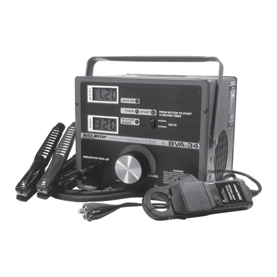
- Page 1 ® Quality Test Equipment Since 1957 OPERATOR’S MANUAL...
-
Page 2: Table Of Contents
Congratulations! On your new purchase of Auto Meter’s Charging/Starting System Analyzer. It is designed to test each component of a vehicle’s electrical system with speed and accuracy. If you should have any questions about your tester or the testing procedures, please give us a call at (815) 895-8141. -
Page 3: Controls And Functions
CONTROLS AND FUNCTIONS VOLTS SELECTOR SWITCH LOAD ON LIGHT START TIMER initiates the switches volt reading from internal indicates load is 15 second timer light when battery clamps to external volt leads being applied. pushed, then released. INDICATOR LIGHT when used in conjunction with the start timer button, indicates when 15 seconds has elapsed. -
Page 4: Orientation / Maintenance
ORIENTATION / MAINTENANCE If tester has not been used for awhile, moisture TESTER CARE AND may have condensed between carbon pile discs. MAINTENANCE This will cause the tester to steam a little during first or second load application. This is normal and Do not lay the inductive Amp probe on is not a malfunction of the tester. -
Page 5: Safety
SAFETY SAFETY PRECAUTIONS: A. SAFETY Carefully read all operating instructions before using. Wear eye protection when working around batteries. Load knob must be off before attaching or removing load clamps to prevent arcing and potential explosion. LOAD Keep sparks, flames or cigarettes away from batteries. VISuAL CHECk Keep hair, hands, and clothing as well as tester leads and cords Inspect For:... - Page 6 BATTERY LOAD TEST 1. HOOk-up FOR 2. ZERO 3. LOAD BATTERY 4. READ 5. TuRn OFF BATTERY LOAD TEST AMMETER VOLTS LOAD (IF nECESSARY) LOAD LOAD arrow on probe LEAVE THE COOLING FAN ON FOR 15 SECONDS, WITH LORD 3. TIMER BLACK OFF TO REDUCE OVER HEATING.
- Page 7 TESTER hOOk-UP SET VOLT SWITCH TO INTERNAL SET VOLT SWITCH TO INTERNAL SET VOLT SWITCH TO EXTERnAL 12 VOLT SYSTEM WITH 12 24 VOLT SYSTEM WITH 12 12 VOLT SYSTEM WITH 6 IMpORTAnT VOLT BATTERIES VOLT BATTERIES VOLT BATTERIES IMPORTANT: IMPORTANT: IMPORTANT: Inductive Amp...
-
Page 8: Hook-Up
STARTER DRAW TEST 1. HOOk-up 2. ZERO 3. DISABLE 4. CRAnk 5. READ AMpS TESTER AMMETER IGnITIOn EnGInE (IF nECESSARY) See “D” Tester Hook-up Crank engine for 3-5 secs. The starter draw test measures the amount 1.Tester hook-up see instruction ‘D” for hook-up. of current needed to crank the engine which 2. -
Page 9: Charging System Overview
ChARGING SYSTEM OVERVIEW When the engine is operating, the charging system converts mechanical energy into electrical energy to supply all of the car’s electrical systems as well as to maintain the battery at full charge. The main components of the charging system are: an alternator (or generator), a regulator, a battery, an in-dash indicator, and the wiring. - Page 10 ALTERNATOR OUTPUT TEST 6. READ MAX. 1. HOOk-up 3. TuRn On 5. CHECk 4. SLOWLY AMp OuTpuT OF TESTER kEY AnD STATOR DIODE AppLY LOAD ALTERnATOR. THEn READ kEY See “D” Tester Hook- TuRn OFF LOAD. DRAW (AMpS) THEn START 2.
-
Page 11: Regulator Bypass Test (Full Field)
REGULATOR BYPASS TEST (FULL FIELD) 1. ZERO 3. START 4. SLOWLY 5. READ MAX 2. FuLL FIELD ALT AMMETER EnGInE AppLY LOAD AMp OuTpuT (use Full Field Adaptor) (IF nECESSARY) OF ALT. Field Term Plug. See “D” Tester Hook-up LOAD Volt Reg. -
Page 12: Amp Draw Test
VOLTAGE REGULATOR TEST The voltage regulator test can 1. HOOk-up 3. READ 2. START be performed as a continuation of the alternator output test. It TESTER & ZERO VOLTAGE EnGInE provides a means of assuring AMMETER that the regulator is suppling (IF nECESSARY) the proper amount of voltage after the car has warmed up. - Page 13 VOLTAGE DROP TEST (FOR STARTING SYSTEMS) Loose or corroded terminal connections and damaged 2. Set volt selector switch as indicated in the diagram. or undersized wires can produce resistance which 3. Hook-up external leads to the part of the circuit being causes the voltage to drop between starting system tested (see following diagrams for specific hook-up).
- Page 14 VOLTAGE DROP TEST (FOR ChARGING SYSTEMS) Loose or corroded terminal connections and damaged 4. Apply load by turning load knob clockwise. Increase or undersized wires can produce resistance, which load until ammeter reads the manufacturers causes the voltage to drop between charging systems specification for alternator output.
-
Page 15: Battery Charging Guide
APPENDIX I BATTERY CHARGING GUIDE nOTE: CHARGInG RATES VARY Recommended charging rates for AnD DEpEnD On THE: fully discharged batteries. The battery capacity rating (in minutes): Battery Reserve Charge Battery At: The higher the rate... the longer the charging Capacity (min.) (slow charge on top time required. -
Page 16: Warranty And Service Information
Also, protect the meters and add plenty of overpack cushioning, such as crumpled up newspaper. AuTO METER pRODuCTS, InC. 2650-792X-10 Rev. C 413 W.
Need help?
Do you have a question about the BVA-34 and is the answer not in the manual?
Questions and answers