
Related Manuals for AST AD511

Summary of Contents for AST AD511
- Page 1 AD511 Active Iridium Antenna User Manual Mar 12 V4.0 AD511 Active Iridium Transmitter/Receiver Antenna with up to 160 metres of coaxial down-lead and DC Power Break-In Box for Iridium Satellite Systems...
-
Page 2: Table Of Contents
Figures ........................8 Figure 1. AD511 Active Iridium antenna ..............8 Figure 2. AD511 Active Iridium antenna with mounting bracket and coaxial down-lead........................8 Figure 3. AD510-40 Power Break-In Box for use with +18 to +36 v DC supply..9 Figure 4. -
Page 3: Fcc Approval
FCC Approval FCC 15.19 (a) (3) This device complies with Part 15 of the FCC Rules. Operation is subject to the following two conditions:- (1) This device may not cause harmful interference, and (2) This device must accept any interference received, including interference that may cause undesired operation. -
Page 4: Ices-003
Réorienter ou déplacer l'antenne de réception. Augmenter la distance entre l'équipement et le récepteur. Brancher l'équipement dans une prise sur un circuit différent de celui auquel le récepteur est connecte Consulter votre revendeur ou un technicien radio / TV pour assistance. ICES-003: This Class B digital apparatus complies with Canadian ICES-003. -
Page 5: Introduction
4mm thick GRP radome mounted on a common base. One antenna is for signal transmission and one for reception. AD511 has a linear power amplifier within the base and connected to the transmitting antenna compensates for signal loss incurred mainly by the connecting cable. -
Page 6: Mounting And Operation
2. The bracket is shipped inverted on the end of the AD511 antenna and should be detached, turned over, then repositioned either to the centre or end of the antenna case as required using the mounting holes in the base. - Page 7 protected against output short-circuiting by a fuse, which is resettable by disconnecting the unit from the +18 to +36 v DC supply. With all connections made, the telephone can then be turned on and used as normal - it is transmitting into a load impedance equivalent to a matched passive antenna.
-
Page 8: Figures
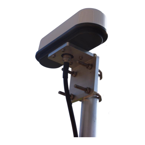
Figures Figure 1. AD511 Active Iridium antenna Figure 2. AD511 Active Iridium antenna with mounting bracket and coaxial down-lead Figures | Applied Satellite Technology... -
Page 9: Figure 3. Ad510-40 Power Break-In Box For Use With +18 To +36 V Dc Supply
Figure 3. AD510-40 Power Break-In Box for use with +18 to +36 v DC supply. The case is hard anodised aluminium and has fixing flanges. A 40m coil of RG213U cable is shown connected to an AD511 active antenna (top). The handset interconnect is shown trailing from the TNC to the bottom left, whilst the flying lead for connection to 18 to 36 v DC supply is shown cutting the frame to the left. -
Page 10: Figure 4. Schematic Diagram For System Connections
Figure 4. Schematic diagram for system connections Mount AD511 active antenna with clear view of sky using bracket supplied. Attach top end of coax down-lead to N type connector on underside of antenna. Attach bottom end of down-lead to N type connector to the Power Break-In Box AD510-40 .
Need help?
Do you have a question about the AD511 and is the answer not in the manual?
Questions and answers