
Summary of Contents for Camera Axe Camera Axe 5
- Page 1 Camera Axe 5 User Manual Document Version: 5.3.1 July 21, 2012 Authors: Maurice Ribble and Andrew Morgan...
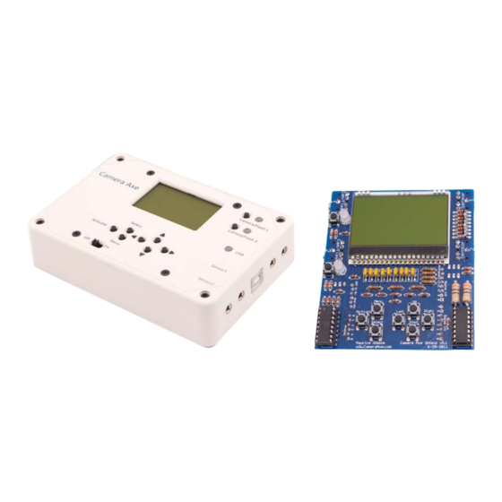
- Page 2 Introduction Differences between Camera Axe 5 and Camera Axe 5 Shield Hardware Display Power Switch Activate Button Select Button Menu Button Arrow/Cursor Buttons Camera Flash Buttons Camera/Flash LEDs Camera/Flash Ports Sensor Ports USB Port Menus Enabling or Disabling Menus Advanced Sensor Menu...
- Page 3 Differences between Camera Axe 5 and Camera Axe 5 Shield The Camera Axe 5 is a fully assembled and tested device. Units shipped after July 1, 2012 use 6 AA batteries or can be powered from the USB cable, but the USB cable does not charge the batteries. It is suggested if running this version of the Camera Axe off the USB cable to turn the power switch off (it will stay on and run completely off the power provided from the USB cable).
- Page 4 Power Switch The shield version has no power switch. To turn the power on/off on the shield version you can either add a switch between the battery providing power to the Arduino or just unplug power from the Arduino. The power switch turns on/off the unit. When the unit is powered on it goes through a startup sequence.
- Page 5 The tip of the 3.5mm plug is +5V, the base of the 3.5 mm plug is ground, and middle of the 3.5 mm plug is the sensor. Starting with Camera Axe 5 (Camera Axe 4 does not support this) the power pin can also optionally be configured as another analog data pin which...
- Page 6 ● analogRead – This returns an analog value between 0 and 1023 proportional to the sensor voltage of 0 to 5 volts. The Camera Axe displays values from 0 to 999. This is the slower way to read the sensor value (still quite fast at 20 microseconds) but it provides the ability to read the range of values from the sensor.
- Page 7 of code from CameraAxe.ino. #define USE_ADVANCEDMENU #define USE_PROJECTILEMENU #define USE_VALVEMENU #define USE_INTERVALOMETERMENU //#define USE_GRAVITYMENU //#define USE_IRREMOTEMENU //#define USE_STACKERMENU //#define USE_PANORAMAMENU //#define USE_JOGMENU If there is a “//” in front of the lines then the menu is removed. If those slashes are not there then that menu is included.
- Page 8 The table below shows the different settings available for each parameter and a brief description of the function of that parameter. Parameter Options Description Trigger Sensor Sensor1 This setting determines which sensor triggers the Sensor2 device. For example, if Device1 is set with Trigger S1_or_S2 Sensor = Sensor1 then when sensor 1 is triggered, S1_and_2...
- Page 9 Trigger Type A setting of Low will trigger when the sensor High reading is lower than the setting. Threshld A setting of High will trigger when the sensor Digital reading is higher than the setting With a Threshld setting, when you activate the sensor it records the base value and then a trigger happens when a difference greater than the threshold value is recorded.
- Page 10 Projectile Menu This menu is a special purpose menu for the projectile sensor. The menu parameter settings are described in the table below. Projectile Menu Distance 06.0 Low/High Trigger Distance Units Inch (Projectile Menu - Values highlighted in black are modifiable.) Parameter Options Description...
- Page 11 V1 Drop1 Size V1 Drop2 Delay V1 Drop2 Size V1 Drop3 Delay V1 Drop3 Size Flash Delay V2 Start Offset V2 Drop1 Size V2 Drop2 Delay V2 Drop2 Size Flash Delay Auto Inc Number of Shots Sec Between Shots NUmber of Repeats (Valve Menu - Values highlighted in black are modifiable.) The following settings are useful for a 1 valve setup.
- Page 12 V1 Drop3 Size Numeric value The number of milliseconds that the valve will be between 000 and open to release the third drop. Flash Delay Numeric value The number of milliseconds to wait after the between 000 and second drop to trigger the flash. The following settings are only useful for advanced users with 2 valve sensors.
- Page 13 Number of Shots Numeric value This is the number of increments to the Flash between 000 and Auto Delay Inc setting above that will be made. It is also the number of shots to be taken automatically unless Number of Repeats is set to non zero.
- Page 14 Interval hours:minutes:seconds The amount of time between shots in hours, minutes and seconds. # Shots (0=Inf) Numeric value between The total number of intervals that will be 0000 and 9999 done. Setting this to 0 will take keep taking shots until this mode is exited or the Camera Axe runs out of batteries.
- Page 15 When the unit is set to turn off the backlight after 10 seconds, pressing the Activate button to enter photo mode will also turn off the backlight. The backlight is the largest contributing factor to power usage on the Camera Axe so turning it off greatly extends battery life. General Settings v5.3...
-
Page 16: Other Menus
If this option isn’t working it means you should manually trigger your camera in bulb mode instead of having the Camera Axe do the triggering of the camera. - Page 17 Sony. To trigger these cameras via IR a special IR module must be plugged into the Camera Axe. There is no official version of this module available for the Camera Axe yet, but there are some people on the forums who have made such modules and can explain how to make your own.
- Page 18 (Jog Menu - Values highlighted in black are modifiable.) Sensors There are a wide variety of sensors that can be used with the Camera Axe. Depending on the sensor type and the menu being used, a wide variety of photographs can be taken using the Camera Axe.
- Page 19 (or you may choose to set up the camera for the shot in manual mode). These Camera Axe settings will trigger a shot each time the daylight dims by 10 units on the light sensor. The camera will be triggered with no delay for 1 second (but the shutter time will be based on the camera settings), with no additional time for pre-focus.
- Page 20 When using the Advanced Sensor menu as described above, when the laser is plugged into a sensor port on the Camera Axe, it can be turned off just before triggering the flash to keep the laser light from being in the shot.
- Page 21 Microphone Sensor The microphone sensor is a basic sound activated sensor that is used to trigger devices based on sharp/loud sound changes. An example of how the microphone sensor would be used is described below. Using a microphone sensor plugged into the Sensor 2 port and a flash connected to Camera/Flash 1, the user would like the flash to trigger 1/2 second after the microphone triggers.
- Page 22 NOTE: This menu uses the readSensorDigitalFast method to read the sensor values and depends on the internal processor thresholds to determine if the sensor is high or low. For more information on using the projectile sensor with the Camera Axe see this article: http://diyphotography.net/bullet-photography-at-home Valve Sensor The valve sensor allows taking pictures of droplets of liquid.
- Page 23 When connecting the valve sensor you want to plug it into the Sensor1 port on the Camera Axe. To trigger your camera there are two options. The first is to trigger it manually with a fairly long exposure like 5 seconds just before you activate the valve sensor. The second option (and I think this is a little easier) is to connect your camera to the Camera Axe's Camera/Flash 1 port and put your camera's exposure to bulb so the Camera Axe can trigger your camera.
- Page 24 Clip Sensor This Clip sensor, which plugs into either of the sensor ports on the Camera Axe, is a generic sensor for people who want to make their sensor. This sensor can trigger the Camera Axe when the conductivity between the clips changes.
- Page 25 Multi-Flash Board This board plugs into the one of the Camera Axe's Camera/Flash ports and replicates that signal to up to 4 more devices. Normally that would be 4 flashes, but it could be 4 cameras. Each device is isolated from the other devices so it is safe to use this with devices that have different trigger voltages.
Need help?
Do you have a question about the Camera Axe 5 and is the answer not in the manual?
Questions and answers