
Summary of Contents for Traficon TrafiCam
- Page 1 User guide TrafiCam TI (9 wires) 10-6030/31: TrafiCam - revision R6.00 TI (9 wires) - revision R2.00 TrafiCam PC Tool - version V2.03 TrafiCam firmware - version V2.10 TrafiCam with TI (9 wires) Manual release: May 2009...
-
Page 2: Safety Warning
TrafiCam with TI (9 wires) Safety warning EN55022 FCC Part 15 Warning This is a class A product. In a domestic environment this product may cause radio interference in which case the user may be required to take adequate measures. - Page 3 The information contained in this document is subject to change without notice. Traficon n.v. makes no warranty of any kind with regard to this material, including, but not limited to, the implied warranties of merchantability and fitness for a particular purpose.
-
Page 4: Table Of Contents
Hardware specification TrafiCam ........ -
Page 5: Introduction
TrafiCam is easy to install and mount on existing or new infrastructure. Configuration is done via TrafiCam PC Tool. A video image from the sensor allows accurate positioning of multiple presence detection zones. TrafiCam provides an input to the traffic light controller upon presence detection. -
Page 6: Hardware
TrafiCam with TI (9 wires) 2. Hardware The TrafiCam system items Items of the TrafiCam system 1 = The TrafiCam sensor 2 = The mounting accessories 3 = Tools (hex keys and cable tags) 4 = The installation CD (with the PC tool and the user guides) - Page 7 TrafiCam with TI (9 wires) Architecture of the TrafiCam system...
-
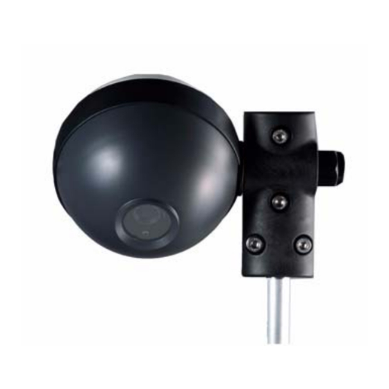
Page 8: The Traficam Sensor
B = The gland to insert the connection cable between sensor and interface C = The sensor LED Front and side view of the TrafiCam sensor CN1, CN2 = The connectors to the TI (9 wires) interface CN1, CN2 pinout: see next. - Page 9 TrafiCam with TI (9 wires) The tables below illustrate the pinout of the connectors CN1 and CN2 and the indicator code of the TrafiCam LED. Pinout of connector CN1 Pinout of connector CN2 Description Description + Power supply Output 1...
-
Page 10: The Interface
The interface = The LEDs for outputs 1 to 4 B = The power LED J1 = The connector to the TrafiCam sensor J2 = The connector to the PC J3 = The service connector J4 = The connector to the traffic controller... -
Page 11: The Cables For Connection
TrafiCam with TI (9 wires) The cables for connection The table below gives an overview of the cables used for connecting the TrafiCam sensor, the interface and the PC. Connection Cable Illustration Sensor to interface UV-resistant, 9 wires + shielding STP, cable d. -
Page 12: Installation
TrafiCam with TI (9 wires) 3. Installation Do not remove the lens cover until TrafiCam is installed. Ensure that the system power is off before starting the installation. Step I: Mount the TrafiCam sensor on a stable pole. • Fix the mounting tube to the brackets (Torque max = 1,3 Nm). -
Page 13: Step Ii: Connect The Traficam Sensor To The Interface
TrafiCam with TI (9 wires) Step II: Connect the TrafiCam sensor to the interface. Use a shielded twisted pair cable, UV-resistant, 10 wires+shield. At the TrafiCam side: • Open the sensor. • Loosen the cable gland. • Insert the cable into TrafiCam through the gland. -
Page 14: Step Iii: Mount The Interface By Clicking It On The Din Rail
Use the RS-232 to RS-485 converter cable and the DB9 serial cable. Finally connect the power supply and remove the TrafiCam lens cover. You optimise the position of TrafiCam via visual verification (TrafiCam PC Tool, see next). Always verify that there is no horizon in the image! -
Page 15: Maintenance
TrafiCam with TI (9 wires) 4. Maintenance The maintenance of TrafiCam can be done during the regular maintenance of the traffic lights and controller. Instruction Frequency Tools Remark Clean faceplate Once per year Soft cloth mild Avoid movement TrafiCam. detergent TrafiCam. -
Page 16: Software Installation
TrafiCam with TI (9 wires) 5. Software installation TrafiCam is set up with TrafiCam PC Tool. This PC tool is available from the installation CD delivered with TrafiCam. Install TrafiCam PC Tool • Insert the TrafiCam installation CD in the CD-ROM drive. -
Page 17: The Work Area Of Traficam Pc Tool
TrafiCam with TI (9 wires) 6. The work area of TrafiCam PC Tool TrafiCam PC Tool - Sensor mode A: Title bar B: Menu bar C: Status bar D: the TrafiCam sensor image 2: the vehicle presence detection zones How to... -
Page 18: Set Up The Traficam Sensor
A zone is displayed according to its detection mode. Zone displayed according to its detection mode: presence (left), stop (middle) and loop (right) The factory default setup of the TrafiCam sensor is displayed when you first open TrafiCam PC Tool. This default configuration has one presence detection zone. -
Page 19: Edit The Default Presence Detection Zone
If you wish to delete the zone direction: double-click the direction point. TrafiCam PC Tool assigns an output to the zone automatically. The number in the zone refers to the assigned output. To change the assigned output: right-click the zone and select an output from the drop-down menu. -
Page 20: Activate The Setup Of Traficam
TrafiCam starts a learning cycle. The learning cycle takes a few minutes. During the learning cycle all presence detection zones are active and the outputs change their status accordingly. When you View the detection a message will indicate that TrafiCam is learning. After the learning cycle the system becomes operational. - Page 21 TrafiCam with TI (9 wires) Guidelines to edit the zones ALWAYS VERIFY THAT THERE IS NO HORIZON IN THE IMAGE! SIZE AND POSITION OF THE ZONE The zone should have the length and the width of a regular vehicle. For detection at the stop bar place the zone as such that the vehicle will stop in the middle of the zone.
-
Page 22: Advanced Settings
TrafiCam with TI (9 wires) 8. Advanced settings The advanced settings of the TrafiCam sensor are either not activated or a default value is assigned. Depending on specific local situations modifications may be useful. Please contact your supplier before changing the advanced setup parameters. -
Page 23: The Filtering Functions
Camera movement suppression This function avoids unwanted detection in a situation where TrafiCam is moving (mounted on a pole that may be swinging because of the wind). You set the level of suppression. A high level may reduce the detection sensitivity. - Page 24 TrafiCam with TI (9 wires) Default: 240 s Selection: 10-600 s Detection LED You can stop the indicator function of the detection LED. Default: Enabled Selection: Disabled, Enabled...
-
Page 25: Other Functions
9. Other functions View the detection TrafiCam PC Tool allows to view live detection on the whole video image or on a single presence detection zone. Traficon recommends to use this function only for diagnostic purposes; viewing live detection may reduce the performance of the TrafiCam sensor. -
Page 26: Set The Vehicle Counting Function
• Click OK. Set the vehicle counting function TrafiCam provides a vehicle counting function based on pulses which are sent to the controller. The number of pulses corresponds with the number of vehicles, the length of the pulse indicates the zone occupancy. -
Page 27: Save Or Load The Setup Of A Traficam Sensor
• Click OK. Save or load the setup of a TrafiCam sensor You can save the complete setup of the TrafiCam sensor as an XML file for backup purposes, for electronic exchange or to copy the setup to another TrafiCam sensor. -
Page 28: Load A Configuration To The Traficam Sensor
TrafiCam sensor. Change the colour of the zones The display colour of the zones in TrafiCam PC Tool is set by default. Proceed as follows if you wish to change these colours: •... -
Page 29: Hardware Specification Traficam
TrafiCam with TI (9 wires) 10.Hardware specification TrafiCam CAMERA CMOS, black & white, sensor 1/3”, resolution 640x480, frame rate 30 FPS LENS TYPE > Wide angle Narrow angle Focal distance 3,0 mm 8,0 mm Field of view - horizontal 95°... -
Page 30: Hardware Specification Ti (9 Wires)
L x H x W: 8 cm x 8 cm x 4 cm; DIN-rail clickable Mass: 100 g COMMUNICATION RS-485 between TI (9 wires), PC and TrafiCam OUTPUTS 4 optical coupled dry contacts (detection output) (Pmax = 300 mW, Imax = 50 mA, Umax = 48 V DC) -
Page 31: Appendix
The height and position of TrafiCam are important factors for minimizing occlusion. Occlusion occurs when a vehicle blocks out part of the field of view of TrafiCam. Please contact your supplier if you wish more information on how to reduce or avoid occlusion. -
Page 32: The Detection Area In Relation To The Camera Height And The Minimum Detection Distance
80 ft 80 ft 15 m 25 m 25 m 25 m 25 m 49 ft 80 ft 80 ft 80 ft 80 ft Maximum detection distance for TrafiCam with a wide angle lens - metric (left) and imperial (right) - Page 33 216 ft 250 ft 46 ft 118 ft 160 ft 196 ft 250 ft 49 ft 114 ft 150 ft 183 ft 250 ft Maximum detection distance for TrafiCam with a narrow angle lens - metric (top) and imperial (bottom) units...
-
Page 34: Appendix 2: Output Wiring Diagram
TrafiCam with TI (9 wires) Appendix 2: Output wiring diagram The TrafiCam device has 4 optical coupled dry contacts which serve as outputs. Via TrafiCam PC Tool you can set the outputs to open or close upon presence detection. The scheme below illustrates the wiring diagram for the outputs. - Page 35 Live viewing 21 Maintenance 11 Outputs assigning TrafiCam outputs 15 setting the output relation 15 TrafiCam, changing the output mode 15 PC port for communication 12 Presence zones adding or deleting a zone 15 assigning an output 15 defining the zone direction 15...
Need help?
Do you have a question about the TrafiCam and is the answer not in the manual?
Questions and answers