VOLTCRAFT AT-200 Operating Instructions Manual
Digital multimeter
Hide thumbs
Also See for AT-200:
- Operating instructions manual (62 pages) ,
- Operating instructions manual (30 pages)

Related Manuals for VOLTCRAFT AT-200


Summary of Contents for VOLTCRAFT AT-200
- Page 1 ® Digital Multimeter AT-200 BEDIENUNGSANLEITUNG Seite 4 - 22 Digital Multimeter AT-200 OPERATING INSTRUCTIONS Page 23 - 41 Multimètre numérique NOTICE D’EMLPOI Page 42 - 60 Best.-Nr. / Item no. / de commande: 12 15 02 Version 08/12...
-
Page 3: Introduction
We are certain: your start with Voltcraft will at the same time be the commencement of a long and profitable co-operation. We wish you much enjoyment with your new Voltcraft ®... -
Page 4: Table Of Contents
Unfavourable ambient conditions are: - excessive dampness or humidity - dust or combustible gases, vapours or solvents - electrical storms or stormy conditions and strong electrostatic fields, etc. Use other than that described above will damage the product and may involve other risks, such as short circuit, fire and electric shock etc. -
Page 5: Safety Instructions
Safety Instructions Please read the complete instructions carefully before starting operation. The information contained is important for correct ope- ration. The warranty will lapse in case of damage caused by failure to comply with these operating instructions! We shall not be held lia- ble for any consequential damage or loss! We do not accept any liability for personal injury or damage to pro- perty caused by incorrect handling or non-observance of the safety... - Page 6 In commercial institutions, the accident prevention regulations of the Employer’s Lia- bility Insurance Association for Electrical Systems and Operating Materials are to be observed. In schools, training centres, computer and self-help workshops, handling of measu- ring instruments must be supervised by trained personnel in a responsible manner. Always make sure before measuring voltages that the measuring instrument is not set to a current measuring range.
-
Page 7: Product Description
It must be assumed that the safe operation is no longer possible, if: - the appliance is visibly damaged - it does not function any longer and - the appliance has been stored for long periods of time under unfavourable conditions - the appliance has been subject to considerable stress in transit. -
Page 8: Scope Of Delivery
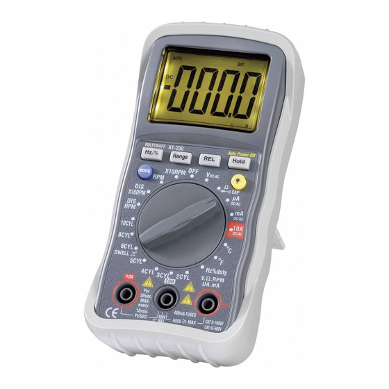
Scope of Delivery Multimeter with protection rubber frame Compound 9V battery K-type thermosensor (up to max. 200°C) Multipurpose plug for the K-type thermosensor Safety measuring wires red and black Safety alligator clips Inductive speed meter Operating Instructions Display Indications and Symbols HOLD stands for data hold;... -
Page 9: Carrying Out Measurements
Carrying out Measurements In no event exceed the max. permitted input values within the over- voltage category III. The frequency of the alternating volumes may not exceed 400Hz! Do not contact circuits or parts of circuits if there could be higher voltages than 25V ACrms or 35V DC pending within them ! Danger! Before measuring, check the connected measuring lines for damage such as, for example, cuts, cracks or squeezing. - Page 10 b) Resistance measurement, diode test,acoustic continuity check and capacity measurement Make sure that all the circuit parts, switches and components and other objects to be measured are disconnected from the voltage and currentless at all times. Proceed as follows for the measurement: - Connect the black measuring line with the COM socket (7) and the red measuring line with the VΩ-socket (6) till they are plane at the measuring instrument.
- Page 11 c) Frequency measurement In no event exceed the max. permitted input values. Do not contact circuits or parts of circuits if you measure voltages higher than 25V ACrms or 35V DC pending within them. Proceed as follows to measure the frequency: - Connect the black measuring line with the COM socket (7) and the red measuring line with the VΩ-socket (6) till they are plane at the measuring instrument.
- Page 12 e) Current measurement in the µA- and mA ranges You can measure currents of up to 400µA in the µA range and currents of up to 400 mA in the mA range. Both current measuring ranges are provided with fuses and thus protected against overload.
- Page 13 f) Current measurement in the 10A range In this range, currents of up to 10A DC/AC can be measured. The current meas - urement range is provided with a fuse and thus protected against overload. Proceed as follows to measure direct currents: - Connect the black measuring line with the COM socket (7) and the red measuring line with the 10A socket (8).
- Page 14 g) Speed measurement The speed can be measured at petrol engines with and without ignition distributors. The speed is measured in an inductive manner at an ignition cable by means of a clamp-on meter. Use this function only for insulated cables to avoid possible contacts! When connecting make sure that wires or clothes, hair etc.
-
Page 15: Special Functions
Special Functions Auto power OFF function In order to avoid that the operating life of the battery is shortened unnecessarily, an automatic switch-off function has been implemented. If a button has not been pres- sed or the rotary switch has not been activated for more than 35 minutes, the mea- suring instrument will be switched off. -
Page 16: Replacing The Battery
roded Moreover the vapours are detrimental to health and explosive. Nor should sharp-edged tools such as screwdrivers, metal brushes etc. be used for cleaning purposes. Periodically check the technical safety of the instrument and measuring lines, e.g. check for damage to the housing or squeezing etc. Always observe the following safety instructions before cleaning the device: Live components may be exposed if covers are opened or parts are removed (unless this can be done without tools). -
Page 17: Replacing The Fuse
Disposal of flat batteries/accumulators! You as the ultimate consumer are legally obliged (Regulation on Spent Batteries) to return all dead batteries and accumulators. Disposal in the household waste is prohibited! Batteries/accumulators containing hazardous substances are marked by the opposite symbols. These symbols also indicate that it is prohi- bited to dispose of these batteries in the household waste. -
Page 18: Troubleshooting
Troubleshooting By purchasing the Digital Multimeter AT-200, you have acquired a product which has been designed to the state of the art and is operationally reliable. Problems and malfunctions may, however, arise. For this reason, the following is a description of how you can eliminate possible mal- functions yourself. -
Page 19: Technical Data And Measurement Tolerances
Technical Data and Measurement Tolerances Technical data Display -digit LCD Speed of measurement : 2 measurements / sec. Input resistance : approx. 10MΩ Battery replacement symbol : <7.5V +/- 0,5V Acoustic signal : for each button activation Battery required : 9V compound battery, NEDA 1604 or 006P type Operating temperature : 0°C to 50°C Storage temperature... - Page 20 400 mA +/-(1.8%+3dgt) 0.1mA +/-(2.5%+5dgt) 0.001 A 10 A +/-(2.5%+5dgt) 0.01 A Overload protection: µA/mA 0.5A 250V quick-acting fuse 10 A 250 V quick-acting fuse Duration of measurement in the 10A range: 0 up to </=5 A permanent measurement > 5A max. 30 sec with a pause of 15 min AC ampere 400 µA +/-(1.5%+3dgt)
- Page 21 Temperature -20°C to +200°C +/-(3%+4dgt) 1°C -4°F to +1400°F +/-(3%+4dgt) 1°F K-type thermosensor Specification of the measuring precision without sensor Speed RPM 600 to 4000 +/-(2%+4dgt) 1 RPM X10RPM 600 to 12000 +/-(2%+4dgt) 10 RPM Speed RPM DIS 300 to 4000 +/-(2%+4dgt) 1 RPM X10RPM DIS...