Table of Contents
Advertisement
SERVICE MANUAL
Read this manual carefully, especially precaution on microwave energy, and follow the procedure
strictly. Careless servicing and testing may expose yourself to the microwave energy leakage.
PRECAUTIONS TO BE OBSERVED BEFORE AND DURING SERVICING TO AVOID
POSSIBLE EXPOSURE TO EXCESSIVE MICROWAVE ENERGY
(a) Do not operate or allow the oven to be operated with the door open.
(b) Make the following safety checks on all ovens to be serviced before activating the magnetron or
other microwave source, and make repairs if necessary:
(1) Interlock operation, (2) proper door closing, (3) seal and sealing surfaces (arcing, wear, and
otherdamage), (4) damage to or loosening of hinges and latches, (5) evidence of dropping or
abuse.
(c) Before turning on microwave power for any service test or inspection within the
microwave generating compartments, check the magnetron, wave-guide or transmission line,
and cavity for proper alignment, integrity, and connections.
(d) Any defective or misadjusted components in the interlock, monitor, door seal, and microwave
generation and transmission systems shall be repaired, replaced, or adjusted by procedures
described in this manual before the oven is released to the owner.
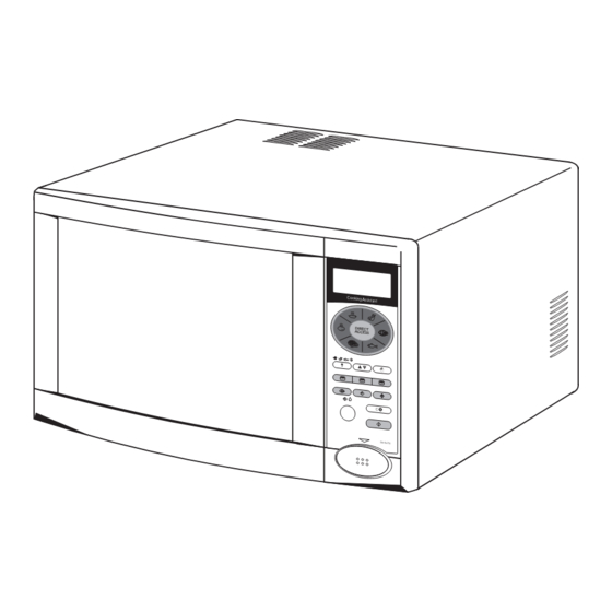
MICROWAVE OVEN
WITH GRILL
Coo king Assis
tant
DIRE CT
ACC ESS
1
2
3
4
150w
450w
/
C
EM-G47 50
FOREWORD
PRECAUTIONS
FILE No.
EM-G4750EES
EM-G4750ECO
Cooking Assistant
DIRECT
ACCESS
1
2
3
4
150w
450w
/
C
EM-G4750
Product Code No.
EM-G4750EES
43748809
EM-G4750ECO
43748812
SM
REFERENCE No.
-850213
Advertisement
Table of Contents

Related Manuals for Sanyo EM-G4750EES


Summary of Contents for Sanyo EM-G4750EES
- Page 1 FILE No. SERVICE MANUAL MICROWAVE OVEN EM-G4750EES WITH GRILL EM-G4750ECO Cooking Assistant DIRECT ACCESS Coo king Assis tant DIRE CT ACC ESS 150w 450w 150w 450w EM-G47 50 EM-G4750 Product Code No. EM-G4750EES 43748809 EM-G4750ECO 43748812 FOREWORD Read this manual carefully, especially precaution on microwave energy, and follow the procedure strictly.
-
Page 2: Table Of Contents
TABLE OF CONTENTS Adjustment Procedures........1 Circuit Diagram............ 4 Specifications............2 Test Procedures and Troubleshooting....5-12 Power Output Measurement........ 2 Disassembly Instructions........13-14 Precautions and Repair Service Tips....2 Exploded View and Parts list........15-19 Oven Control Panel..........3 Control Circuit Board..........20 Overall Circuit Diagrams........21 CAUTION MICROWAVE ENERGY PERSONNEL SHOULD NOT BE EXPOSED TO... -
Page 3: Specifications
2. SPECIFICATIONS - EM-G4750 4.PRECAUTIONS AND REPAIR SERVICE TIPS Rated Power Consumption..Micro 1450±10%W PRELIMINARY Grill 1100+5/-10%W Dual 2500+5/-10%W A.SINCE NEARLY 4,000 VOLTS EXIST IN (After 15mins.) SOME CIRCUITS OF THIS MICROWAVE Microwave Output...... 900W( Adjustable 90W OVEN, REPAIRS SHOULD BE CARRIED through 900W ) OUT WITH GREAT CARE Frequency........ -
Page 4: Oven Control Panel
5. OVEN CONTROL PANEL Cooking Assistant DIRECT ACCESS 150w 450w EM-G4750 Figure 1 KEYS: weight or enter the time of day. 11. Delay Start Key 1. Display Window 3. Auto Menu Programs. 12. Microwave Power 2. Indicators: 4. Kitchen Timer 13. -
Page 5: Circuit Diagram
6.CIRCUIT DIAGRAM EM-G4750 (Europe) 230V ~ 50Hz OVEN CONDITION DOOR : OPEN L1,L2 = 1mH C1 = 0.22µF TOUCH KEY C2,C3 = 4700PF BOARD R = 1MΩ S101 MTCO CFTCO(122˚C) FUSE (8A T) CONTROL C RCU T BOARD HT(150˚C) R (25Ω) H GH VOLTAGE TRANSFORMER MAGNETRON 2M-219H(B)Z- H V FUSE 0 75A... -
Page 6: Test Procedures And Troubleshooting
7. TEST PROCEDURES AND TROUBLESHOOTING Filament Windings CAUTION - DISCONNECT THE POWER SUPPLY CORD FROM THE WALL OUTLET WHENEVER REMOVING THE CABINET FROM THE UNIT. PROCEED WITH THE TESTS ONLY AFTER DISCHARGING Secondary Winding THE HIGH VOLTAGE CAPACITOR AND REMOVING THE LEAD WIRES FROM THE PRIMARY WINDING OF THE HIGH VOLTAGE TRANSFORMER. - Page 7 COMPONENT CHECKOUT PROCEDURE RESULTS 1) Measure the resistance : Normal readings : With an ohmeter on Rx1 scale. a. Primary Winding ; Approximately 1.7 ohms. b. Filament Winding ; Less than 1 ohm. c. Secondary Winding ; Approximately 92 ohms. 2) Measure the resistance : Normal readings : With an ohm-meter on highest scale.
- Page 8 COMPONENT CHECKOUT PROCEDURE RESULTS Measure the resistance : Across two terminals with an ohm-meter on its highest scale. Normal reading : Indicates continuity. HV FUSE Abnormal reading : Indicates infinite ohms. Figure 10 Measure the voltage : Between test points TP-1,TP-2, and ground (See control circuit board on page 20 ).
- Page 9 CHECKOUT PROCEDURE FOR SWITCHES Disconnect the lead wires from the switches and check the continuity of the switches, connecting an ohm-meter to its terminals. SWITCH CHECKOUT PROCEDURES DOOR OPEN DOOR CLOSE Primary Interlock Connect an ohm-meters leads to terminals "COM" and "NO"...
- Page 11 -10- -10-...
- Page 12 -11- -11-...
- Page 13 -12-...
-
Page 14: Disassembly Instructions
8.DISASSEMBLY INSTRUCTIONS C. REMOVING MAGNETRON (See exploded view on page 16 ) - OVEN MUST BE DISCONNECTED FROM ELECTRI- (1) Remove the antenna complete according to CAL OUTLET WHEN MAKING REPLACEMENTS, B. REMOVING THE ANTENNA. REPAIRS, ADJUSTMENTS, AND CONTINUITY (2) Disconnect the 2 lead wires from the magnetron. CHECKS BEFORE PROCEEDING WITH ANY REPAIR (3) Remove 1 screw securing the duct to the WORK AFTER DISCONNECTING. - Page 15 4. The hinge screws should then be tightened to hold the (3) Remove power cord from cavity assembly by door in place, and the feeler gauges removed. lifting cord bush, moving it to the left and pulling it 5. The door gap should then be checked again using feeler away from cavity rear plate.
-
Page 16: Exploded View And Parts List
8. EXPLODED VIEW AND PARTS LIST CAVITY PARTS EM-G4750 Part No. Description Q'ty Part No. Description Q'ty 1 617 188 0595 Cabinet 13 617 221 0025 Heater Complete 2 411 156 5601 SCR TPG PAN+F+S 4x10 14 617 202 4554 Thermostat, 150˚C 3 617 221 2814 Cavity 15 617 167 0431 Duct... - Page 17 SWITCHES AND MICROWAVE PARTS EM-G4750 Part No. Description Q'ty Part No. Description Q'ty 411 010 5600 SCR EVR PAN 3x6 617 167 5627 Lever Stopper 411 156 5601 SCR TPG PAN+F+S 4x10 617 220 4529 Door Sensing Switch 411 156 5502 SCR S-TPG PAN+F+S 4x10 617 220 4536 Interlock Monitor Switch...
- Page 18 MICROWAVE PARTS EM-G4750 Part No. Description Q'ty 617 209 4557 Transformer 617 225 1721 Special Screw 617 220 7957 Bottom Plate ------------------ Gear Motor Cover 617 144 5435 Foot Cushion Assembly 617 166 7493 Bottom Hinge 411 156 5602 SCR S-TPG PAN+F+S 4x10 3 -17-...
- Page 19 DOOR PARTS Inner Door Pane a ways O 2 @ @ @ @ @ 6 K ? O 2 @ @ @ @ @ @ @ @ @ @ @ @ @ 6 K ? ? W & @ @ @ @ @ @ @ @ @ @ @ @ @ @ @ @ @ @ @ @ @ @ @ @ @ @ @ @ @ @ @ @ @ @ @ @ @ @ @ @ @ @ @ @ @ @ @ 6 X O 2 @ @ @ @ @ @ @ @ @ @ @ @ @ @ @ @ @ @ @ @ @ @ @ @ @ @ @ @ @ @ @ 6 K ? W 2 @ @ @ @ @ @ @ @ @ @ @ @ @ @ @ @ @ @ @ @ @ @ @ @ @ @ @ @ @ @ @ @ @ @ @ @ @ @ @ @ @ 6 K ? O 2 @ @ @ @ @ @ @ @ @ @ @ @ @ @ @ @ @ @ @ @ @ @ 6 K...
- Page 20 CONTROL PANEL PARTS A u t D e f. D u a l G r il l T im S t a r 1 5 0 3 0 0 4 5 0 7 0 0 8 0 0 EM-G4750 Part No. Description Q'ty Part No.
-
Page 21: Control Circuit Board
10.CONTROL CIRCUIT BOARD EM-G4750 Continental Version. Model Version Spares No. M.Processor EM-G4750 Spain 617 222 6736 LM8842 Semo -20-... -
Page 22: Overall Circuit Diagrams
11. OVERALL CIRCUIT DIAGRAM EM-G4750 Continental Model. IC 11 LM8842 -21-... - Page 23 Please Note All the information that appears in this service manual was correct at the time of production. SANYO Electric Manufacturing reserves the right to make changes to parts or processes in order to maintain their policy of continuing improvement.
Need help?
Do you have a question about the EM-G4750EES and is the answer not in the manual?
Questions and answers
How we can grill chicken