
Summary of Contents for caron 6220
- Page 1 6220 & 6240 SERIES FREEZE / THAW CHAMBER OPERATIONS MANUAL FOR MODELS 6220, 6221 6240, 6241 PO Box 715 Marietta, OH 45750 800-648-3042 740-373-6809 Fax 740-374-3760 www.caronproducts.com service@caronproducts.com...
- Page 2 At CARON, we are committed to continuous quality improvement. Our goal is to supply our customers with highly reliable equipment at a fair price. In order to openly monitor our performance, we would appreciate your feedback on our products and services.
-
Page 3: Table Of Contents
TABLE OF CONTENTS Section 1 – Warranty ..................5 Section 2 – Equipment Overview ..............8 Section 3 – Installation ................10 Unpacking Choosing a Location Preliminary Cleaning Installing the Port Stopper Installing the Shelves Leveling the Unit Connecting the Drain Line Connecting the Water Supply Connecting Electrical Power Connecting Communications and Analog Outputs... - Page 4 Section 7 – Calibration ................45 Calibrating the Temperature Calibrating the Humidity Calibrating Optional Chart Recorders Section 8 – Alarms ..................47 Alarm System Overview Changing Alarm Set-points Section 9 – Preventative Maintenance ............48 Section 10 – Specifications ................ 49 Section 11 –...
-
Page 5: Section 1 - Warranty
Caron Products & Services, Inc. (herein after CARON) hereby warrants that equipment manufactured by CARON is free from defects in materials and workmanship when the equipment is used under normal operating conditions in accordance with the instructions provided by CARON, as follows: COVERED: ... - Page 6 Damage from chemicals or cleaning agents detrimental to equipment materials. Force Majeure or Acts of God. This writing is a final and complete integration of the agreement between CARON and the customer. CARON makes no other warranties, express or implied, of merchantability, fitness for a particular purpose or otherwise, with respect to the goods sold under this agreement.
- Page 7 INTERNATIONAL SYMBOLS AND DEFINITIONS Help Information Warning of hazardous area Warning of hot surface Warning of dangerous electric voltage Earth (ground) protective conductor WARNINGS Local government may require proper disposal 6200 series Operations Manual Rev D 2/14/2012 Page 7 of 60...
-
Page 8: Section 2 - Equipment Overview
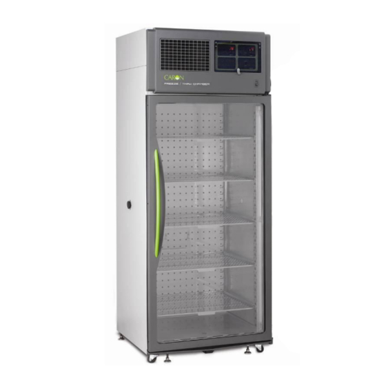
Before using the equipment, familiarize yourself with key components of the product and thoroughly read this manual. Replaceable air Lockable intake filter Control Panel Power Illuminated Switch CARON Logo Adjustable Sliding Shelf Left Side Access Port Right Side Access Port Door Handle Temperature (& Humidity) Sensors Casters &... - Page 9 SECTION 2 – EQUIPMENT OVERVIEW -- CON TINUED Humidity Temperature Humidity Controller Controller Enable Switch Visual Alarm Options Indicator Alarm Silence Panel Switch 6200 series Operations Manual Rev D 2/14/2012 Page 9 of 60...
-
Page 10: Section 3 - Installation
Choose a location where these facilities are, or can be made available. If a water source, or a drain is not available, contact CARON customer service and ask about our CRYS102 product line or click this weblink for information on the product: http://www.caronproducts.com/65... -
Page 11: Preliminary Cleaning
Additional shelving can be purchased through CARON customer service if necessary. To install the shelf channels insert the rear tab on the shelf channel into the rear wall on the side wall of the chamber. -
Page 12: Leveling The Unit
3/8” plug into the drain connection. Connecting the Water Supply To ensure proper operation, distilled or deionized water is required as a supply on units that have humidity control. If these water sources are not available contact CARON customer service. 6200 series Operations Manual... -
Page 13: Connecting Electrical Power
Use only distilled or deionized water with a resistivity between 50K-CM and 1M-CM and a pH of greater than 6.5. Using water outside this range will void your warranty. Do not use water that contains chloramines. Chloramines can damage internal rubber gaskets resulting in leaks. -
Page 14: Connecting Communications And Analog Outputs
Connecting Communications & Analog Outputs This unit comes standard with features such as RS485 communications and analog outputs. A set of terminals are provided to connect to RS485 communications and analog outputs. Analog Outputs Analog outputs are either milliamps (0-20mA, 4-20mA) or voltage (0-5V, 1-5V, 0-10V, 0-20V) signal output that represents each of the displayed temperature (and humidity) values. - Page 15 Standard Bus. The maximum number of chambers connected to a single PC is limited to 247 controllers (Modbus) or 16 controllers (Standard Bus). Chambers 6221 & 6421 have one controller each. Chambers 6220 & 6420 have two controllers each. Connect...
-
Page 16: Section 4 - Optional Accessory Installation
With the purchase of ALRM301, a set of terminals on the rear of the unit is provided to monitor temperature and humidity (6220 & 6240 only) alarms. With the alarm contacts, the terminals provided allow for a NO (normally open) output, a NC (normally closed) and COM (common) connection. -
Page 17: Installing The Carboy Water System (Botl301)
Installing Carboy Water System (BOTL301) Models 6220 & 6240 can be purchased with an optional 2.5 gallon carboy water system. The carboy system is preassembled and shipped inside the chamber. The four ¼” bolts required to mount the carboy to the unit will be mounted in the left hand side of the chamber. -
Page 18: Installing The Heatless Dryer Package (Dryr301)
Installing the Heatless Dryer Package (DRYR301) The Heatless Dryer Package extends the operational limits to a minimum humidity control point of 2% RH and improves the dehumidification rate by purging the chamber with dry air. Air flows through the Dryer Package only when dehumidification is required to maintain the humidity set point. - Page 19 Incoming compressed air must not exceed 100 psig. CARON recommends installing a pressure gauge, filter, and shutoff prior to the dryer to monitor incoming air pressure. The air supply (either house air or other compressed air source) must be 90 to 100psig at the air supply inlet. An oil-less compressor may be used.
- Page 20 3. Attach 3/8” orange tubing from the chamber to the flow meter outlet. Flow Meter Outlet 4. Connect compressed air to dryer package inlet fitting (1/4 NPT) Dryer Inlet See Operations section of the manual for instructions on setting the pressure regulator and flow meter.
-
Page 21: Connecting The Fluorescent Lighting (Lght301 & Lght305)
Connecting the Fluorescent Lighting (LGHT301 & LGHT305) Chambers with optional fluorescent lighting have light banks consisting of two lamps each. 6220 series models have three independent light banks and 6240 series models have four light banks on two independent controls. The light banks are suspended to the shelf underside. -
Page 22: Installing Drain Water Pump (Pump301)
Installing Drain Water Pump (PUMP301) In applications where a floor drain is not available and a CARON water recycling system is not being used, a drain pump can be purchased to pump any excess condensate from the chamber to a local sink or drain. The pump is located near the middle of the back of the chamber. -
Page 23: Section 5 - Operation
SECTION 5 – OPERATION With the chamber properly installed and the appropriate utilities connected, the power switch on the lower right of the control bezel can be turned on. Within a few minutes, the temperature and humidity will begin to approach set-points. Allow the unit to stabilize for 12 hours before use or prior to making any calibration adjustments. -
Page 24: Changing The Humidity Set-Point
Changing the Humidity Set-point (6220 & 6240 only) Actual Increase Humidity Humidity Set-point Humidity Set-point Decrease Humidity Set-point Enable Humidity Control Switch EZ Button To set the humidity set-point, press the UP arrow to increase the humidity set-point by 1% RH. - Page 25 This temperature ‘spike’ is normal and assures long-term operation. Operation in Low Temperature Mode (6220 & 6240 only) When the chamber is operating at temperatures below 4.5C, it automatically enters the Low Temperature Mode. In this mode, the humidity control and display is disabled because of the risk of water freezing and causing damage.
-
Page 26: Operation Of The Delux Controller System
Operation of the Delux Controller System The chambers can be purchased with upgraded controllers. The controllers have additional features of RS485 communications, analog outputs, and ramp & soak. RS485 Communications: Each controller on the network (connected to the same PC or master device) must be programmed with a unique address. - Page 27 Analog Outputs: With DLUX301 & DLUX302 controllers, there is an analog output signal for temperature and humidity which represents the actual chamber values. This allows the chamber to be connected to an in-house data acquisition or alarm system. The analog signal outputs are selectable as either voltage DC or milliamp. In both cases, the output is scalable from 0.0 to 20.0.
- Page 28 Set the Scale Low value to correspond with the minimum value of the process output in electrical units. For 0-5V, set to 0. For 1-5V, set to 1. For 4-20mA, set to 4. Set the Scale High value to correspond with the maximum value of the process output in electrical units.
- Page 29 Ramp & Soak: A ramp and soak control system is included with DLUX301 & DLUX302 controllers. This allows the user to store up to 40 steps spanning 4 profiles. A step consists of a change in set-point (or ramp). Another step is used to maintain a set-point for a fixed duration (or soak).
-
Page 30: Section 6 - Optional Accessory Operation
SECTION 6 – ACCESSORY OPERATION Using the Carboy Water System (BOTL301) To fill the carboy while attached to the chamber, unscrew the cap. Fill carboy with distilled or deionized water (see Connecting the Water Supply section for details). The carboy holds 2.5 liters. If the carboy must be removed in order to fill it up, first disconnect the tubing between the carboy and chamber by pressing the metal lever at the tubing connects / disconnects at the bottom of the carboy. -
Page 31: Operation Of The Heatless Dryer Package (Dryr301)
Operation of the Heatless Dryer Package (DRYR301) The flow meter shows the flow rate of dry air entering the chamber. It is adjustable by the knob at the bottom of the meter. Maximum performance is obtained at 300 SCFH (or 5 CFM). Operating the unit above or below this purge rate may decrease performance!! A pressure regulator is installed between the tower dryers and glass flow meter to limit the pressure into the flow meter. - Page 32 Each light bank has a corresponding switch that enables that light bank to come on when the timer is on. The 6220 series have three independent controls while the 6240 series have two. Only the light banks that have their individual switch turned on will illuminate.
- Page 33 Operating the timer The power switch enables and disables the lights and cycle timer. When the timer is “on”, the 2 set-point (also known as “idle set point”) on the controllers is enabled as well as the lights. The timer will display “OUT” corresponds to lights being enabled. The timer has an adjustable “on”...
- Page 34 Accumulate or Reset Factory default is set so the timer continues where it left off after a power cycle (accumulate). This prevents the timer from re-starting in the event of an electrical brown-out or power outage. To change the setting so the timer re-starts to zero when power is cycled, follow the steps below.
-
Page 35: Controlling The Led Lighting (Lght302)
Controlling the LED Lighting (LGHT302) The LED lighting system creates low-level internal lighting. There are separate temperature and humidity (optional) set-points that correspond with the lights on (day) and lights off (night). The set-points can also be made the same if continuous conditions are needed throughout the light cycles. - Page 36 Operating the timer The power switch enables and disables the lights and cycle timer. When the timer is “on”, the 2 set-point (also known as “idle set point”) on the controllers is enabled as well as the lights. The timer will display “OUT” corresponds to lights being enabled. The timer has an adjustable “on”...
- Page 37 Examples for how to start your timer during day or night modes Night Start Procedure: 1. Set the timer to SET 1 2. Enter the length of time you would like the lights off (night setting) Example 12 Hrs. 3. Set the timer to SET 2 4.
- Page 38 Accumulate or Reset Factory default is set so the timer continues where it left off after a power cycle (accumulate). This prevents the timer from re-starting in the event of an electrical brown-out or power outage. To change the setting so the timer re-starts to zero when power is cycled, follow the steps below.
-
Page 39: Interior Electrical Outlet (Outl301 & Outl302)
Interior Electrical Outlet (OUTL301 & OUTL302) An optional interior duplex electrical outlet is available to supply power to small interior appliances such as shakers or stirrers. It is not intended to power high current draw devices. The outlet is 115V and GFI protected. For chambers that have a single interior duplex outlet, the outlet is fused at 2.0 Amps. -
Page 40: Operation Of The Front 10" Mounted Recorders (Rcdr303 / Rcdr304)
Operation of Front Mounted 10” Recorders (RCDR303, RCDR304) Built in 10” thermal pen recorders can be purchased with CARON chambers. The recorders are shipped installed on the outer door of the chamber from the factory and require no further installation. Unlike ink pen recorders, the thermal recorders draw their own chart and control lines. - Page 41 save all of the changes that have been made to the recorder's configuration. The thermal pen arm will move off of the chart allowing you to place the recording chart paper onto the recorder. Press and release the Change Chart button to begin recording.
- Page 42 Recorder Calibration: If calibration is required for single input recorders, use the Left (#1) and Right (#2) arrow buttons on the recorder to calibrate the temperature being recorded on the chart to correspond to the temperature of the solution. The arrow buttons must be held for approximately eight (8) seconds before the pen begins to move.
-
Page 43: Operation Of Thermal Side Mounted Recorders (Rcdr314, Rcdr315)
Operation of Thermal Side Mounted Recorders (RCDR314, RCDR315) Side mounted Honeywell DR 4500 Truline Circular Chart Recorders are also available with CARON chambers. This chart recorder uses reliable microprocessor operation to generate dependable thermal traces on universal 12-inch (310 mm) charts. The two- input models (RCDR315) accepts inputs from a temperature sensor and a humidity sensor. - Page 44 4. Press the FUNC button and ‘CHRT SPD’ will show 5. Use the up and down arrow keys to select one of the standard settings (8 hr, 12 hr, 24 hr, 7 days) or ‘x HR’ to specify a unique speed. 6.
-
Page 45: Section 7 - Calibration
If the unit has been in operation, allow a minimum of 3 hours of stable operation at all set-points. If you do not have the appropriate reference instruments to perform calibration, contact CARON’s service department for on-site calibration at . Caron also provides validation services which ensures that service@caronproducts.com... -
Page 46: Calibrating The Humidity
Calibrating the Humidity If humidity calibration is needed, the following steps can be taken: Infinity Key Advance Key Locate the reference instrument’s temperature sensor in close proximity to the cabinet’s geometric center. Be sure that the stabilization times described earlier have been satisfied prior to performing this calibration. -
Page 47: Section 8 - Alarms
SECTION 8 – ALARMS Alarm System Overview The chamber control system is equipped with an alarm system that constantly monitors temperature, and humidity (on humidified models) to ensure the user is notified if the cabinet goes into an alarm condition. Notification occurs via a RED indicator light and an buzzer. -
Page 48: Section 9 - Preventative Maintenance
The CARON chamber has been robustly designed to minimize performance problems. However, regular maintenance is very important for continuous trouble free operation. As a general rule, CARON recommends an annual calibration check of the temperature, and humidity systems. CARON offers a full range of on-site calibration and validation services. -
Page 49: Section 10 - Specifications
Four (4) Five (5) Shelf Construction Type 304 Stainless Steel, Electro polished, Shelf Dimensions 29" W x 24" D (74cm x 62cm) Model 6220 & 6221 6240 & 6241 Shipping Weight 575 lbs. 875 lbs.** 650 lbs. 950 lbs.** Electrical... -
Page 50: Section 11 - Electrical Schematics
SECTION 11 – ELECTRICAL SCHEMATICS 6200 series Operations Manual Rev D 2/14/2012 Page 50 of 60... - Page 51 SECTION 11 – ELECTRICAL SCHEMATICS (CONTINUED) 6200 series Operations Manual Rev D 2/14/2012 Page 51 of 60...
-
Page 52: Section 12 - Troubleshooting
SECTION 12 – TROUBLESHOOTING Problem -- Unit will not turn on Is the unit connected to a dedicated electrical circuit as defined in the installation section of the manual? Is there power at the electric outlet the unit is plugged into? Is the unit’s power switch turned on? Problem -- Unit temperature is above / below temperature set-point Has the unit’s temperature set-point been recently lowered / raised and if so has the... -
Page 53: Section 13 - Spare Replacement Parts
SECTION 13 – SPARE / REPLACEMENT PARTS General Part Number Description MTR-130 Blower Motor BLW-112 Blower Wheel (6220 & 6221) BLW-114 Blower Wheel (6240 & 6241) CTR-134 Watlow Delux Controller POW-108 24V DC Power Supply FLTR301 Condenser Filter Replacement Kit... - Page 54 Fuse Related Description 230V Main circuit breaker switch CBR-116 (12A) FUS1 Front mount chart recorder fuse FUS-155 (0.08A) FUS2 Side mount chart recorder fuse FUS-156 (0.16A) FUS3* Internal outlet fuse (single duplex) FUS-151 (2A) FUS3* Internal outlet fuse (double duplex) FUS-163 (4A) FUS5* Int.
-
Page 55: Section 14 - Advanced Users Section
SECTION 14 – ADVANCED USERS SECTION Unlocking the Controllers The temperature and humidity controllers are factory programmed for precise control. Unlocking the controllers gives the user access to all parameters. Modifying parameters that are not thoroughly understood can adversely affect chamber performance that will not be covered under warranty. -
Page 56: Appendix A - Ramp & Soak Programming Example
APPENDIX A – RAMP & SOAK EXAMPLE General An efficient way to program a profile is to first outline what the temperature controller should do. If the chamber has humidity control, an outline should be generated for this too. Example of a temperature profile outline: Profile 1 Step 1 Ramp to 20ºC as quickly as possible... - Page 57 9. Use the UP and DOWN arrow buttons to define each parameter and the ADVANCE button to go to the next parameter. The parameters are described below: Parameter Description Display Target set-point Set point for this step t9.SP Hours Number of hours for a timed step hoUr Minutes Number of minutes for a timed step...
- Page 58 Step 2 Soak step type S.tyP SoAH Time in hours hoUr Time in minutes Time in seconds Event Output 1 Ent1 Event Output 2 Ent2 Step 3 Rate step type S.tyP rAtE Target set-point (50ºC) T9.SP Ramping rate (1ºC per minute) rAtE Event Output 1 Ent1...
- Page 59 Step 8 Un-used step S.tyP UStP Step 9 Un-used step S.tyP UStP Step 10 Un-used step S.tyP UStP 6200 series Operations Manual Rev D 2/14/2012 Page 59 of 60...
-
Page 60: Appendix B - Declaration Of Conformity
DECLARATION OF CONFORMITY Caron Products and Services, Inc. 27640 State Route 7 Marietta, OH 45750 USA Declares that the product: Designation: 6220 & 6240 Series Model Numbers: 6220-3, 6221-3, 6240-3, 6241-3 Classification: Electrical equipment intended for residential, commercial and lighting industrial...
Need help?
Do you have a question about the 6220 and is the answer not in the manual?
Questions and answers