Advertisement
Quick Links
Advertisement

Summary of Contents for Origen ae X10
- Page 1 user guide Origen...
-
Page 3: User Guide
OrigenAE is not responsible for any damages due to external causes, including but not limited to, improper use, problems with electrical power, accident, neglect, alteration, repair, improper installation or improper testing. Revision X10.V2.11/06 Copyright © 2007 OrigenAE Technology. All rights reserved... -
Page 4: Table Of Contents
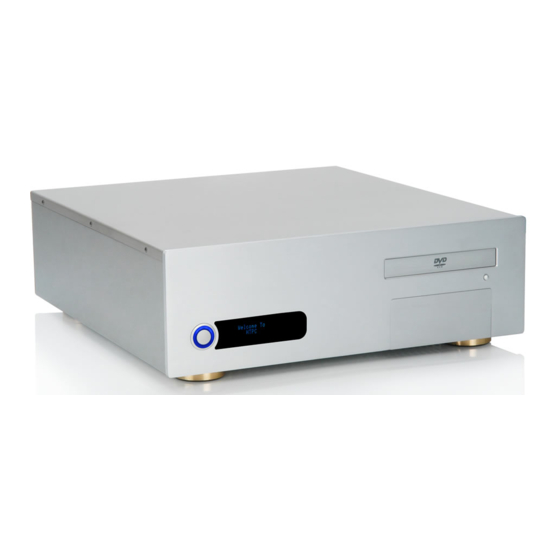
X10 overview Opening the case Removing drive cage Removing PSU bracket PSU and drive installation Optical drive bezel installation Front ports cable diagram VFD/IR cable diagram VFD/IR module installation oftware installation Installing VFD/IR driver Installing VFD/IR software... - Page 5 X10 overview X10 overview. Front view highlighting features and controls. External dimensions (WxHxD) 435x150x460mm Motherboard support Drive bays 1 x 3.5” internal, 1 x 3.5” + 1 x 5.25” external 11 12 PSU support PCI / AGP card support HTPC power button...
-
Page 6: Removing Drive
Opening the case / Removing drive cage & PSU bracket Opening the case. To remove the lid of the case, undo the 4 screws indicated. Removing drive cage & PSU bracket. This will need to be done before the drives and PSU can be installed and is achieved by removing the screws as indicated in the diagram. - Page 7 (3) and screwing in place. Hard drive Drive installation procedure. The X10 supports 1 x hard drive, 1 x optical drive and 1 x 3.5” drive. The 3.5” bay can be used for a media drive or any other size device.
-
Page 8: Optical Drive Bezel
Optical drive bezel installation Optical disk drive bezel installation. The X10 is supplied with an aluminum optical drive bezel to match the finish of the case. The installation procedure requires that the plastic drive bezel that comes fitted on your drive be removed and replaced with the aluminum X10 drive bezel. -
Page 9: Front Ports Cable
Front ports cable diagram Front ports cable diagram. VCC 1 The X10 provides front audio, DATA+ 1 USB1 USB, and 1394 ports DATA- 1 motherboards that support GROUND 1 these connections . There are 3 cables that can be VCC 2... -
Page 10: Vfd/Ir Cable
VFD/IR cable diagram VFD/IR cable diagram. This is a general overview of the cable layout connecting the VFD/IR module, power switch (power button) and motherboard . Please refer to your motherboard manual for the location of the correct ports and header pins. Power switch IN Power switch OUT Programming pin (do not use) -
Page 11: Vfd/Ir Module
VFD/IR module installation VFD/IR module installation procedure. This should be done once the motherboard has been fitted, and before the power supply has been installed. Standby ATX power cable. This cable is required to draw a standby current from the PSU when the PC is off. This allows the IR module to function when the power is off, and turn the PC on remotely. -
Page 12: S Oftware
VFD/IR Software Installation. You will require the CD provided to begin the installation of the VFD/IR software, and you should select the X10 option from the main menu to begin. There are 2 steps required to install the necessary software to operate the VFD/IR:... -
Page 13: Installing Vfd/Ir
Installing VFD/IR driver Installing VFD/IR driver. Prior to running the VFD/IR software, the driver must be installed. This is done by following the procedure below. When the VFD/IR Make sure ‘Search for Browse to your ROM DRIVE and select the folder ‘VFD module is connected the best driver in these Driver’, then Click ‘OK’. - Page 14 Installing VFD/IR software Installing VFD/IR Software. The software installation is started by clicking the link shown on the Installation CD. Follow the steps below to complete the installation. Installing Software Select language. When the IR software is running, this icon will be displayed in the taskbar.
- Page 15 notes...
- Page 16 Origen Contact Details #209 Baeksan B/D 763-2 Hengsin-Dong Dukyang-Gu Goyang City Gyounggi-Do 412-220 South Korea Global Product Support e-mail:support@origenae.com Website www.origenae.com...
Need help?
Do you have a question about the X10 and is the answer not in the manual?
Questions and answers