Table of Contents
Advertisement
Advertisement
Table of Contents
Troubleshooting

Related Manuals for DEC VT420

Summary of Contents for DEC VT420
- Page 1 VT420 Service Guide Order Number EK–VT420–PS.002 Digital Equipment Corporation...
- Page 2 Printed in U.S.A. The following are trademarks of Digital Equipment Corporation: SSU, VMS, VT, VT52, VT100, VT220, VT320, VT420, and the DIGITAL logo. ADP is a trademark of Automatic Data Processing, Inc. Kodak is a registered trademark of Eastman Kodak Co.
-
Page 3: Table Of Contents
VT420 Models and Features VT420 Models ........ - Page 4 iv Contents Removing and Replacing FRUs Top Cover ........CRT/Yoke/Bezel Assembly .
- Page 5 A–1 VT420 Cables ........
-
Page 7: About This Guide
Appendices provide information on the following topics: Modems, cables, and related documentation VT420 models and recommended spares Physical/functional diagrams Tools Required You need the following tools to service the VT420 video terminal: Tool Part Number Anode discharge tool 29-24717-00 25-pin, RS-232 EIA loopback connector... - Page 8 viii About This Guide Conventions The following conventions are used in this guide: Warnings Provide information to prevent personal injury. Cautions Provide information to prevent damage to equipment. Notes Provide general operating information. Set-up features The names of set-up features appear in bold type. Example: Use the save feature in the Set-Up Directory screen.
-
Page 9: Vt420 Models And Features
VT420 Models and Features 1.1 VT420 Models The VT420 is a monochrome text terminal that provides all VT320 features plus enhancements. The VT420 has a 359 mm (14-inch) diagonal monitor with a flat, antiglare screen. The monitor can display 24, 25, 36, or 48 lines of text in an 80- or 132-column format. - Page 10 • FCC Class A compliance • Two 6-pin, DEC-423 connectors (One is for the primary host port, and one is for the secondary host or printer port. Both have DEC-423 local direct-connect capability.) • Asynchronous communication up to 38.4K bits/second •...
-
Page 11: Vt420 Model Differences
VT420 Models and Features 3 • LK401 keyboard that includes — Right and left keys Alt Function — Right Compose Character — Lock and Hold LEDs Table 1–1 VT420 Model Differences Features FCC Class B compliance AC power cord: Attached Detachable with country-specific plug... -
Page 12: Troubleshooting And Testing
Table 2–1 lists probable causes and solutions for general problems with the terminal. When you turn on the VT420 terminal, it performs a power-up self-test to check for problems. If the test finds an error, the terminal may display an error message at the upper-left corner of the screen (Section 2.4). -
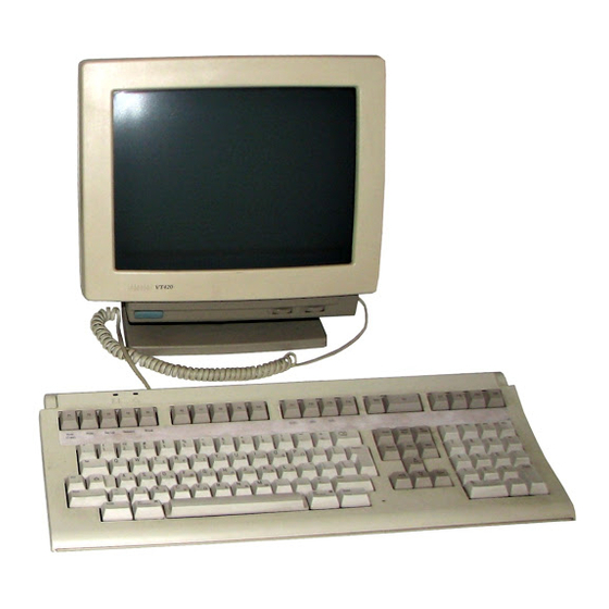
Page 13: Vt420 Video Terminal With Keyboards
Troubleshooting and Testing 5 KEYBOARD 102 LJ-01105-TI0 Figure 2–1 VT420 Video Terminal with Keyboards ANSI (LK401/LK402) keyboard Short ANSI (LK421, UNIX style) keyboard PC (LK443/LK444) keyboard... -
Page 14: Troubleshooting The Vt420
6 Troubleshooting and Testing Table 2–1 Troubleshooting the VT420 Symptom Probable Cause Solution Problems at Power-Up Nothing appears Terminal board. 1. Make sure all connectors on on the screen. the board are seated properly. 2. Replace the terminal board (3.3). - Page 15 Troubleshooting and Testing 7 Table 2–1 (Cont.) Troubleshooting the VT420 Symptom Probable Cause Solution Screen Display Problems Screen is off There is Adjust the screen by using the center or rotated. interference from Screen Align field in the Set-Up electromagnetic Directory screen.
- Page 16 8 Troubleshooting and Testing Table 2–1 (Cont.) Troubleshooting the VT420 Symptom Probable Cause Solution Screen Display Problems The screen is CRT saver feature Press any key to restore the screen blank, except for is activated. display. the blinking block cursor in the lower-right corner.
- Page 17 Troubleshooting and Testing 9 Table 2–1 (Cont.) Troubleshooting the VT420 Symptom Probable Cause Solution Character Display Problems While on-line Incorrect transmit Set the speeds to match the host, in with the host, and receive the Communications Set-Up screen. the screen speeds.
-
Page 18: Vt420 Self-Tests
Section numbers follow the solution. 2.2 VT420 Self-Tests The VT420 has a series of self-tests to determine if the terminal board is the faulty field replaceable unit (FRU). You can run each test from the keyboard by entering the escape sequence for the test. Table 2–2 lists the tests and their escape sequences. -
Page 19: Before You Start
Troubleshooting and Testing 11 2.2.1 Before You Start Before you run any self-test, you must either • Install the appropriate loopback connector on the communication port, Set the terminal to local mode • You should save the current settings in set-up before you run tests. If you are unfamiliar with set-up, see 5, ‘‘Using Set-Up’’. -
Page 20: Vt420 Self-Test Chart
Set the terminal to in the General Set-Up screen. In VT100 Mode VT100 mode, you can press to generate an ESC character. See Chapter 5 for a description on using set-up. Table 2–2 VT420 Self-Test Chart Self-Test Prerequisites Sequence Power-up None Turn the terminal on. -
Page 21: Power-Up Self-Test
1. The keyboard’s LED indicators turn off. 2. The keyboard makes a bell tone. 3. A message appears on the screen. This message disappears VT420 OK when any of the following events occur: • The terminal receives any character except XON, XOFF, or NUL. -
Page 22: Dec-423 Port Loopback Test (6-Pin)
2.2.4 DEC-423 Port Loopback Test (6-Pin) For this test, connect the DEC-423 port transmit and receive data lines together with a loopback connector (Figure 2–2). The terminal sends a predefined set of characters on its transmit line and receives them on... -
Page 23: Vt420 Rear Connector Panel And Loopback Connectors
P i n P i n P i n F r o m P i n P i n G S F _ 1 4 4 8 _ 8 9 . D G Figure 2–2 VT420 Rear Connector Panel and Loopback Connectors... -
Page 24: Rs-232 Port Data Lines Loopback Test (25-Pin, Worldwide Model Only)
1. The keyboard makes a bell tone. 2. The keyboard’s LED indicators turn off. 3. A message appears on the screen. VT420 OK If the test finds an error: The screen displays the following message. See Table 2–3. VT420 RS-232 Port Error -- 2... -
Page 25: Rs-232 Port Control Lines Loopback Test (25-Pin, Worldwide Model Only)
1. The keyboard makes a bell tone. 2. The keyboard’s LED indicators turn off. 3. A message appears on the screen. VT420 OK If the test finds an error: The screen displays the following message. See Table 2–3. VT420 RS-232 Port Controls Error -- 3... -
Page 26: Printer Port Loopback Test (6-Pin)
To run the test: Use a DEC-423 loopback connector, PN 12-25083-01. 1. Set up the terminal (Sections 2.2.1 and 2.2.2). 2. Connect the loopback connector to the 6-pin DEC-423 port. 3. Type the following sequences: ESC [ 4 ; 3 y Runs the test once. -
Page 27: Printer Problems
4. Perform the adjustment procedures in Chapter 4. 2.3 Printer Problems If the VT420 is connected to a local printer, you may have to troubleshoot some printer problems. The following procedure helps you isolate the problem to the printer or the terminal. -
Page 28: Error Codes
Makes the keyboard bell tone sound • Displays an error message in the upper-left corner of the screen Table 2–3 lists the error messages and solutions. Table 2–3 VT420 Display Error Codes Error Message Solution Press ( Alt SetUp ) to enter VT420 NVR Error - 1 the Set-Up Directory. - Page 29 Troubleshooting and Testing 21 Table 2–3 (Cont.) VT420 Display Error Codes Error Message Solution If the error continues, replace the terminal board (3.3). Replace the terminal board (3.3). RS-232 Port Data Error - 2 (worldwide model only) Replace the terminal board (3.3).
-
Page 30: Removing And Replacing Frus
Removing and Replacing FRUs This chapter shows you how to remove and replace the field replaceable units (FRUs) for the VT420. See Appendix B for the recommended spares list. CAUTION Always use a static protection kit (PN 29-26246-00) when handling static-sensitive material. - Page 31 Removing and Replacing FRUs 23 2. Place the terminal facedown on a clean piece of paper, to avoid scratching the bezel. G S F _ 1 4 3 8 _ 8 9 . D G...
- Page 32 24 Removing and Replacing FRUs 3. Loosen the two captive screws at the base of the bezel so the screws extend out from the top cover. G S F _ 1 4 3 9 _ 8 9 . D G 4.
- Page 33 Removing and Replacing FRUs 25 G S F _ 1 4 4 0 _ 8 9 . D G To install the top cover: 1. Extend the captive screws out from the top cover. 2. Slide the top cover into the front bezel so the two tabs on the top of the bezel align with the cover.
-
Page 34: Crt/Yoke/Bezel Assembly
26 Removing and Replacing FRUs 3.2 CRT/Yoke/Bezel Assembly To remove the CRT/yoke/bezel assembly: 1. Turn off the terminal and unplug the power cord from the wall outlet. 2. Remove the top cover (Section 3.1). WARNING The following steps may expose you to high voltages. To protect yourself, discharge the anode with anode discharge tool (PN 29-24717-00). - Page 35 Removing and Replacing FRUs 27 Remove the anode discharge tool. 4. Remove the CRT anode connector from the CRT. a. Grasp the rubber anode cap and push the cap away from you. b. Press the front of the cap with you thumb and lift the front up to get one of the wire prongs out of the anode hole.
- Page 36 28 Removing and Replacing FRUs NOTE If you have a North American model, skip the next two steps. 5. If you have a worldwide model, disconnect the ground clip from the hood. G S F _ 1 4 4 3 _ 8 9 . D G...
- Page 37 Removing and Replacing FRUs 29 6. If you have a worldwide model, loosen the two screws securing the hood and remove the hood. H o o d S c r e w G S F _ 1 4 4 4 _ 8 9 . D G...
- Page 38 30 Removing and Replacing FRUs 7. Disconnect the ground clip from the arc protection board. G S F _ 1 4 4 5 _ 8 9 . D G...
- Page 39 Removing and Replacing FRUs 31 8. Remove the arc protection board from the back of the CRT. G S F _ 1 4 4 7 _ 8 9 . D G CAUTION To prevent damage to terminal board components, be careful when you unlock and remove the yoke wiring harness connector in the next step.
- Page 40 32 Removing and Replacing FRUs 9. Disconnect the locking connector on the yoke wiring harness from the terminal board by pushing the locking tab and pulling the connector. G S F _ 1 4 4 9 _ 8 9 . D G 10.
- Page 41 Removing and Replacing FRUs 33 b. Lift or pull the base away from the CRT/yoke/bezel assembly. G S F _ 1 4 5 0 _ 8 9 . D G To install the CRT/yoke/bezel assembly, reverse the installation steps.
-
Page 42: Terminal Board Assembly
34 Removing and Replacing FRUs 3.3 Terminal Board Assembly To remove the terminal board assembly: CAUTION To prevent damage to internal components, do not replace the fuse if it burns out. A burnt fuse is a symptom of a problem inside the terminal. - Page 43 Removing and Replacing FRUs 35 6. Pull the board away from the plastic tab on the connector side of the terminal board. You can release the tab by inserting a screwdriver through the hole below the tab. 7. Lift the terminal board out of the base. G S F _ 1 4 5 3 _ 8 9 .
-
Page 44: Keyboard
36 Removing and Replacing FRUs 3.4 Keyboard If the keyboard is faulty, replace the keyboard. Turn the terminal off and disconnect the keyboard cable from the keyboard cable connector on the right side of the terminal. Remove and save the legend strip. The PC (LK443/LK444) keyboard does not have a legend strip. - Page 45 Removing and Replacing FRUs 37 5. If you want the keyboard raised up, lower the two legs on the bottom. 6. Turn the keyboard over. Install the legend strip, aligning the strip with the tabs. ANSI (LK401) keyboard: Place the strip below the top-row function keys as shown.
-
Page 46: Crt Disposal (Digital Service Representatives Only)
38 Removing and Replacing FRUs 3.5 CRT Disposal (Digital Service Representatives Only) This section describes how to safely dispose of the monitor’s cathode-ray tube (CRT). NOTE This procedure replaces any other tech tips on replacing and disposing of CRTs. This procedure is for Digital personnel only, and is not intended for use by OEM and self-maintenance customers. - Page 47 Removing and Replacing FRUs 39 Handling a CRT • Never handle the CRT by the neck. Always use two hands and hold the CRT by the sides near its face. • Keep the CRT away from your body during handling. •...
- Page 48 40 Removing and Replacing FRUs Never handle pieces of phosphor coated glass without wearing protective gloves. 1. Place the old CRT and the original packing material in the container from which you removed the new CRT. G S F _ 1 4 5 1 _ 8 9 . D G...
- Page 49 Removing and Replacing FRUs 41 2. Seal up the container so that only the very tip of the CRT neck is exposed. 3. Using the specified pliers, slowly crush, but do not snap, the evacuation point. Do not move or disturb the CRT until the hissing sound of inrushing air has stopped.
-
Page 50: Adjusting The Video Monitor
Adjusting The Video Monitor This chapter describes how to adjust the VT420 monitor. You do not have to perform every adjustment each time you align the monitor. However, you should check all adjustments in the order shown, because many adjustments affect each other. If a setting is already correct, you can skip that adjustment and go on to the next setting. -
Page 51: Set-Up Directory Screens
C o m p o s e W a i t Nort h Am eri can S et -Up Dire ct o ry VT420 A V1. 0 G l obal D i s pl ay Genera l C om m... -
Page 52: Screen Align Screens
G S F _ 1 5 9 0 _ 9 0 . D G Figure 4–2 Screen Align Screens NOTE The North American model of the VT420 does not have the feature to rotate the active display on the screen. -
Page 53: Monitor Adjustments
Adjusting The Video Monitor 45 4. When you have finished centering or rotating the border, return to the Set-Up Directory. Move the cursor to the field. Save 5. Press . This saves all the current settings in each set-up screen. Enter message appears at the bottom of the screen. -
Page 54: Before You Start
3. Turn the power switch on by moving it toward the ( | ). Wait for the message to appear on the screen. VT420 OK 4. Make sure all shields are in place before doing any adjustments. 4.2.2 Displaying the Screen Test Pattern You use the same screen test pattern for all monitor adjustments. -
Page 55: Screen Control
Adjusting The Video Monitor 47 4.2.3 Screen Control To adjust the screen control: 1. On the front of terminal, set the brightness control to maximum and the contrast control to minimum. 2. Adjust the screen control (R657) until the white background (raster) almost disappears, but is still visible. -
Page 56: Rotation And Centering Adjustment
48 Adjusting The Video Monitor 3. Gently rotate the yoke until the display is square and level on the CRT/yoke/bezel assembly. CAUTION Make sure you take up the slack on the CRT clamp before you tighten the screw. Do not overtighten, or you may crack the CRT neck. -
Page 57: Horizontal Width
Adjusting The Video Monitor 49 4.2.6 Horizontal Width Check and adjust the horizontal width as follows. You need a metric measuring tape (PN 29-25342). 1. Display the Screen Align screen by selecting the field in Screen Align the Set-Up Directory screen. 2. -
Page 58: Centering
50 Adjusting The Video Monitor 4.2.9 Centering To check and adjust the centering of the screen display: 1. Display the Screen Align screen by selecting the field in Screen Align the Set-Up Directory screen (Figure 4–2). 2. Follow the instructions on the screen to center the active video display. 3. -
Page 59: Using Set-Up
Using Set-Up The VT420 terminal has a series of set-up screens that let you change the settings of operating features from the keyboard. This chapter provides a brief summary of how to use set-up. The set-up chapter in Installing and Using the VT420 Video Terminal describes the set-up screens in detail. -
Page 60: Set-Up Directory Screens
L o c k C o m p o s e W a i t N ort h A m eri can S et-U p D ir e cto ry VT420 AV1. 0 Global D is pl ay Genera l Com m... -
Page 61: Changing Settings
Using Set-Up 53 5.2 Changing Settings You use the arrow keys to move to different fields in each set-up screen. The cursor highlights the selected field in reverse video. Some set-up features are action fields. Others are parameter fields with two or more possible settings. -
Page 62: Modems, Cables, And Documentation
Modems, Cables, and Documentation You can order the following modems, cables, and manuals from Digital for the North American and worldwide versions of the VT420. See the end of this appendix for ordering information. A.1 Modems Part Number Description DF242 Scholar Plus... - Page 63 Null Modem Cables BC22D-xx – 25-pin F RS-232 to 25-pin F RS-232 Communication Cables BC16E-10 3 m (10 ft) 6-pin M DEC-423 to BC16E-25 7.6 m (25 ft) 6-pin M DEC-423 AC Power Cables Country BN20V-2E Australia, New Zealand BN20S-2E...
-
Page 64: Vt420 Cables
C om m 1 Po rt H8 5 71 -A A d ap te r B C1 6E Ca b l e Hos t G S F _ 1 4 6 5 _ 8 9 . D G Figure A–1 VT420 Cables... -
Page 65: Related Documentation
Installing and Using the VT420 Video Terminal with EK-VT42A-UU PC Terminal Mode Provides users with the information needed to install, operate, and maintain the VT420 terminal with PC terminal mode. Also provides a summary of programming control functions. VT420 Programmer Reference Manual EK-VT420-RM Provides information on character processing, character codes, and control functions available for all VT420 applications including PC terminal mode. -
Page 66: Vt420 Recommended Spares
VT420 Recommended Spares This appendix has two sections. • Section B.1 lists the available models of the VT420 video terminal. • Section B.2 lists the spare components that a Digital service representative should have when servicing a VT420 video terminal. - Page 67 VT420 Recommended Spares 59 Model Screen Power Location Number Color Requirement Southern Hemisphere VT420-A5 White 100 V to 240 V VT420-B5 Green 100 V to 240 V VT420-C5 Amber 100 V to 240 V Israel (Hebrew) VT420-A7 White 100 V to 240 V...
-
Page 68: Recommended Spares
60 VT420 Recommended Spares B.2 Recommended Spares The following is a list of recommended spares for the VT420 video terminal: Part Assembly Number Model Number Tilt-swivel base 70-26541-01 — Top cover 70-26542-01 — Bottom cover 70-26535-01 — CRT/bezel/yoke White 70-26534-04 —... -
Page 69: Keyboard Models
VT420 Recommended Spares 61 Loopback Connector Part Number DEC-423 port 12-25083-01 RS-232 port 12-15336-00 B.3 Keyboard Models The keyboards for the VT420 are available in the following versions: Model Number Country Standard LK401 ANSI Keyboard North America/United Kingdom LK401-AA LK402-AA... - Page 70 62 VT420 Recommended Spares Model Number Country Standard LK443 PC Keyboard Canada (French) LK443-AC — North America LK443-AA — LK444 (PC) Keyboard Australia/New Zealand LK444-AZ — Belgium LK444-AB — Canada (English) LK444-AQ — Denmark LK444-AD — Finland LK444-CA — France LK444-AP —...
-
Page 71: Physical/Functional Diagrams
Physical/Functional Diagrams This appendix shows the components and pin assignments for the North American and worldwide models of the VT420 video terminal. Figure C–1 shows the components of the North American model. Figure C–2 shows the components of the worldwide models. -
Page 72: Vt420 North American Model
D E C - 4 2 3 G S F _ 1 4 6 6 _ 8 9 . D G Figure C–1 VT420 North American Model VT420 North American Model: Signals and Pin Assignments Terminal Board Assembly J1 DEC-423 Comm1 Port Connector HDTR2... - Page 73 Physical/Functional Diagrams 65 DSR2 Data set ready J2 DEC-423 Comm2/Printer Port Connector HPTRDTR Data terminal ready HPTRTXD Transmitted data Transmit ground PTRCOM Receive ground PTRRXD Received data PTRDSR Data set ready J3 Keyboard Port Connector HKBTXD Transmitted data Ground +12 V...
-
Page 74: Vt420 Worldwide Models
G S F _ 1 4 6 7 _ 8 9 . D G L J - 0 1 6 2 8 - T I 0 Figure C–2 VT420 Worldwide Models VT420 Worldwide Model: Signals and Pin Assignments Terminal Board Assembly J1 DEC-423 Comm1 Port Connector HDTR2... - Page 75 Physical/Functional Diagrams 67 DSR2 Data set ready J2 DEC-423 Comm2/Printer Port Connector HPTRDTR Data terminal ready HPTRTXD Transmitted data Transmit ground PTRCOM Receive ground PTRRXD Received data PTRDSR Data set ready J3 RS-232 Comm1 Port Connector Ground HTXD1 Transmitted data...
- Page 76 68 Physical/Functional Diagrams CRT/Yoke/Bezel Assembly J601 CRT Yoke Connector Rotation coil (green) Rotation coil (black) Vertical yoke (brown) Vertical yoke (yellow) Horizontal yoke (white) Horizontal yoke (red) Arc Protection Board Assembly J701 CRT Socket Connector GRN G1 Grid 1 (green) YEL K2 Cathode (yellow) BRN H1...
- Page 77 CRT/yoke/bezel assembly removal, Local mode, selecting, 11 Loopback connectors, 15 Loopback tests printer port, 18 RS-232 port control lines, 17 DEC-423 port loopback test, 14 RS-232 port data lines, 16 Documentation, 57 Modems Error characters Modem speed problems, 10 Reverse question marks, 9...
- Page 78 8 pin assignments, 64 on-line, 8 Screen is blank, 6 Scrolling problems, 7 Self-tests, 10 to 21 DEC-423 port loopback, 14 Olivetti parts, 59, 60 power-up, 13 Operating modes, 2 screen alignment pattern, 18 selecting local mode, 11...
- Page 79 Index 3 overview, 1 part numbers, 58 VT420 rear connector panel, 15 Vertical height adjustment, 49 Vertical linearity adjustment, 49 VT420 features common features, 1 Worldwide model VT420 models components, 65 description, 1 model numbers, 58 differences, 3 pin assignments, 66...
- Page 81 HOW TO ORDER ADDITIONAL DOCUMENTATION From Call Write Alaska, Hawaii, 603–884–6660 Digital Equipment Corporation or New Hampshire P.O. Box CS2008 Nashua NH 03061 Rest of U.S.A. 800–DIGITAL and Puerto Rico Prepaid orders from Puerto Rico, call Digital’s local subsidiary (809–754–7575) Canada 800–267–6219 Digital Equipment of Canada Ltd.
Need help?
Do you have a question about the VT420 and is the answer not in the manual?
Questions and answers