
Summary of Contents for TEM VS 5500 plus
- Page 1 VS 5500 plus Heating controller Operating manual Dok. Nr. 111045 33/2007 "entwurf"...
-
Page 2: Table Of Contents
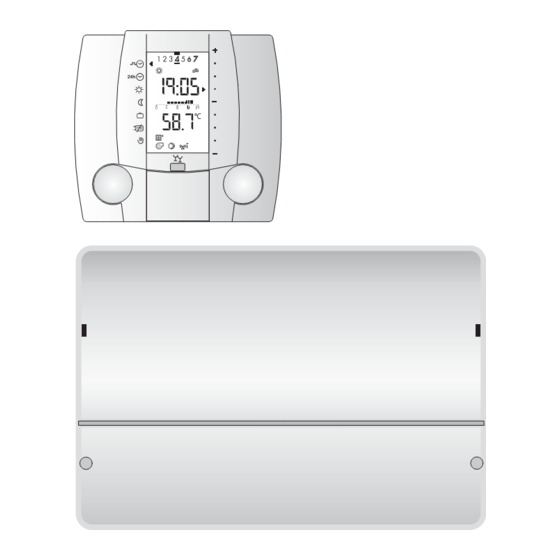
Settings in the coded service level................ 23 Constant values ...................... 26 General points ......................27 6.1 What makes up the VS 5500 plus?................27 6.2 What does the VS 5500 plus control?............... 27 6.3 Hydraulic ........................27 Dimensions and installation................... 28 Explanation of terms and 7.1 Installation VS 5511 plus................... - Page 3 Display und operating elemente Clapet closed Claped open desired room temperature: = normal, = comfort, = reduced Party function Domestic hot water production on/off Days: 1=Monday Daytime 2=Tuesday etc. Arrow marks the selected mode Roomtemperature heating mode adoption (with the right Time bar rotary knob) temperature-/...
- Page 4 Notes:Display und Bedienelemente...
-
Page 5: Operation With The Cover Closed
Operation with the cover closed 1.1 Select operating mode Cover closed The required operating mode can be sel- ected using the left rotary knob. The arrow to the left in the display shows which operating mode is active. Example: 1. The arrow marks the weekly clock programme 2. -
Page 6: Set Room Temperature Temporarily
1.2 Set room temperature temporarily Cover closed The room temperature can be set tem- porarily using the right rotary knob. This adjustment can be made in all operating modes except: • Reduced heating (also in clock pro- gramme) • Holiday programme •... -
Page 7: Activation Of The Holiday Programme
1.4 Activation of the holiday programme Cover closed The holiday programme can be acti- vated in two ways: 1. Select the operating mode "Holiday" using the left rotary knob. 2. Select the automatic holiday programme, see "2.8 Setting the automatic holiday programme", page Active operating modes •... -
Page 8: Activate The Clock Programme Exception Day
1.6 Activate the clock programme exception day Cover closed 1. Select the operating mode Clock programme exception day with the left rotary knob. If the Clock programme exception day is set before 17.00 hrs, it is valid for the whole day. If it is set after 17.00 hrs, it becomes active on the following day, the arrow stays on and blinks on... -
Page 9: Manual / Emergency Operation
1.8 Manual / emergency operation The temperature of the boiler thermostat must be checked before the operating mode Manual / emergency operation is selected! With floor heating, the boiler thermo- stat temperature must not be higher than max. 50 °C. Cover closed The operating mode Manual/emergen- cy operation... -
Page 10: Operation With The Cover Open
Operation with the cover open Open the cover Left rotary knob The links to functions shown on the display can be selected. Right rotary knob The right rotary knob has two functions: 1. Selection of functions shown on the right of the display. 2. -
Page 11: Setting The Date
2.1 Setting the date Open the cover 1. Using the left rotary knob, select the function . The right-hand arrow is already at 2. Push the button, the date blinks. 3. The date can now be set by turning the right rotary knob. 4. -
Page 12: Setting The Clock Time
2.2 Setting the clock time Open the cover 1. Select the function with the left rotary knob. 2. Select the function Time with the right rotary knob. 3. Press the push-button, the time dis- play blinks. 4. The time can now be set using the right rotary knob. -
Page 13: Check Temperatures And Operating Mode
2.3 Check temperatures and operating mode Open the cover 1. The function is selected. • Select the required temperature with the right rotary knob. • The corresponding set value can be shown on the upper line by pressing the push-button. The value for outside temperature shown in the display remains unchanged. -
Page 14: Setting The Weekly Clock Programme
2.5 Setting the weekly clock programme Open the cover 1. Select the function with the left rotary knob. 2. Select the required day/time period with the right rotary knob. • Confirm the day selected with the push-button. 3. Select the required heating tempera- ture with the right rotary knob. -
Page 15: Setting The Clock Programme Exception Day
2.6 Setting the clock programme exception day Open the cover 1. Select the function using the left rotary knob. • Confirm the selection with the push- button. 2. Select the required heating tempera- ture using the right rotary knob. ( is not shown). -
Page 16: Setting The Room Temperature
2.7 Setting the room temperature Open the cover 1. Select the function with the left rotary knob. 2. Using the right rotary knob, select the room temperature be changed. 3. Activate the setting with the push- button. The temperature display blinks. -
Page 17: Setting The Automatic Holiday Programme
2.8 Setting the automatic holiday programme Open the cover 1. Select the function using the left rotary knob. 2. Press the push button, the datum blinks. • The arrows indicate the functions Start holiday programme Date 3. Using the right rotary knob, enter the date for the start of the holiday Year Start... -
Page 18: Settings In The Service Level
Settings in the service level Open the cover 1. Select the function using the left rotary knob. • Press the push-button, the arrow to the right in the display blinks. 2. Set the required control strategy using the right rotary knob. •... -
Page 19: Setting Level 3 - Room Temperature Control Mixed Heating Circuit
3.2 Setting level 3 - Room temperature control mixed heating circuit Set- Function Setting Factory Unit Start-up date: Adjustment ting range setting date: 3:00 Control strategy = Weather control only Selection criterion: Room temperature cannot be measured Configuration: Connect outside temperature sensor = Room control only Selection criterion: Outside temperature cannot be measured... - Page 20 3.2 Setting level 3 - Room temperature control mixed heating circuit Set- Function Setting Factory Unit Start-up date: Adjustment ting range setting date: 3:05 Heating limit during reduced operation -10÷20 °C Only in the clock programme! If the outside temperature exceeds the set value for reduced heating operation , the heating circuit switches to summer operation .
-
Page 21: Setting Level 3 - Room Temperature Control Direct Heating Circuit
3.3 Setting level 3 - Room temperature control direct heating circuit Set- Function Setting Factory Unit Start-up date: Adjustment ting range setting date: 3:01 Flow temperature at outside temperature of 20 °C 10÷80 °C The set value for flow temperature at an outside temperature of 20°C is set here. (base point). The heating curve ˚C 3: 03... -
Page 22: Setting Level 5 - Warm-Water Supply
3.3 Setting level 3 - Room temperature control direct heating circuit Set- Function Setting Factory Unit Start-up date: Adjustment ting range settings date: 3:06 Pre-heating time (optimisation) 0÷990 This ensures that the room temperature has nearly reached the set value already at the start of the heating period. The set value (in minutes) indicates the time difference between start of preheating and start of the heating period. -
Page 23: Settings In The Coded Service Level
Settings in the coded service level Open the cover 1. Select the function with the left rotary knob. 2. Turn the right rotary knob until "Code" appears. 3. Press the push-button, the code entry blincks on the display. 4. Enter the code using the right rotary knob. - Page 24 4.1 Setting level 3 - Room temperature control Set- Function Setting Factory Unit Start-up date: Adjustment ting range setting date: 3:09 Duration party function 0÷250 This setting is used to define the duration of the party function 3:10 Room protection temperature -10÷20 °C This setting is used to define the room protection temperature valid for the holiday programme...
- Page 25 4.3 Setting level 6 - Heat generator (Boiler) Set- Function Setting Factory Unit Start-up date: Adjustment ting range setting date: 6:00 Minimum heat generation temperature 0÷60 °C The set value which the heat generator maintains during operation. 6:04 Maximum heat generation temperature 50÷90 °C The set value which should not be exceeded by the heat generator.
-
Page 26: Constant Values
Constant values The functions and values described in the following can be neither selected or set. It is however necessary to know them, as they have an influence on the functioning of the controller. 5.1 Domestic hot water supply Function Factory setting Unit Over-increase heat generator temperature for the warm-water supply... -
Page 27: General Points
General points 6.1 What makes up the VS 5500 plus? The VS 5500 plus is made up of: • An operating unit SR 5811 • A controller VS 5511 plus • An outside sensor ZAF 500 • A flow sensor ZVF 210 Optional: •... -
Page 28: Dimensions And Installation
Dimensions and installation 7.1 Installation VS 5511 plus Determination of position The VS 5511 plus control unit should be placed as close as possible to the heat generator/heating circuit so that only a short cable is required. Mounting the base plate The base plate of the VS 5511 plus control unit is fastened to the wall using three screws. -
Page 29: Installation Sr 5811
7.3 Installation SR 5811 Determination of position If the SR 5811 is used to record the room Front view Side view temperature, the following positioning open actors should be taken into considerati- • In the reference room on an inside wall with normally heated next room. -
Page 30: Start-Up
7.5 Start-up The mains current connec- Mains current connection functional units (230 VAC): tions to the right no. 1-7/LN are ’live’ Alternative 1 Alternative 2 with 230 Volt. These clips may only be touched if they are not connected to the electricity supply, otherwise there is a danger of fatal electric shock. -
Page 31: Help In Solving Problems
Help in solving problems If no basic display or an error message are shown after switching on, the expla- nations in the following table may be of help. Problem Possible cause Remedy No display Controller not switched on Check the fuses, switch the controller on. External switch is set to manual/emergency Change the switch for manual/emergency operation... -
Page 32: Technical Data
Technical data 9.1 Technical data SR 5811 Supply voltage via Bus cable Ambient operating temperature 0 °C ... 50 °C Bus interface: OpenTherm 2-cable bus, twisted, interchangeable Bus cable, length, cross-section max. 50 m, min. 0,5 mm Certification The controller is conform as per the following EU guidelines: •... -
Page 33: Sensor Resistance Values
9.3 Sensor resistance values Temperature °C Resistance NTC 5 k: 48'535 36’475 27’665 21’165 16’325 12’695 9’950 7’855 6’245 5’000 4’029 2’663 1’802 1’244 9.4 Explanation of terms and abbreviations b1, b2, b3 Time periods which can be set for the clock programme. Hours Actual value Temperature measured... - Page 34 Notes:...
- Page 35 Index Set weekly clock programme 14 Automatic holiday programme setting 17 Settings in the coded service level 23 Settings in the service level 18 Start-up 30 Check heating circuit operating mode 13 Check temperatures and operating mode 13 CLEAR 10 Technical data 32 CLEAR function (factory setting charge) 18 Clock programme activate exception day 8...
- Page 36 Manufacture or distribution:...
Need help?
Do you have a question about the VS 5500 plus and is the answer not in the manual?
Questions and answers