Table of Contents
Advertisement
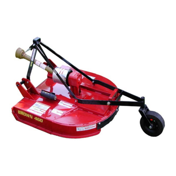
400 Series
Rotary Cutter
ATTENTION:
ALL WARRANTY WORK MUST BE APPROVED
BY BROWN MFG. CORP.
BEFORE WORK BEGINS
Owner / Operator Manual
WARNING
Before operating your machine,
stop and read this owners manu-
al. Do not attempt to operate the
unit until you fully understand the
material covered in this manual.
Without the knowledge contained
in this manual, injury or death can
result.
Advertisement
Table of Contents

Related Manuals for BROWN 460


Summary of Contents for BROWN 460
- Page 1 400 Series Rotary Cutter ATTENTION: ALL WARRANTY WORK MUST BE APPROVED BY BROWN MFG. CORP. BEFORE WORK BEGINS Owner / Operator Manual WARNING Before operating your machine, stop and read this owners manu- al. Do not attempt to operate the unit until you fully understand the material covered in this manual.
- Page 2 This publication may be freely reproduced, either in whole or in part, provided that the content herein is not altered. We encourage you to make copies of this manual and to distribute it to every operator of the machine. Additional copies are also available from Brown Manifacturing Corporation.
-
Page 3: Table Of Contents
Contents Warranty ........................... 4 Registration ........................6 Equipment Safety ......................7 Assembly........................16 Operation ........................18 Maintenance ........................20 Troubleshooting ......................30 Specifications ......................... 31 Replacement Parts ......................32... -
Page 4: Limited Warranty
1. LIMITED WARRANTIES 1.01. . Brown Manufacturing Corp. warrants for one year from the purchase date to the original non-commercial, governmental, or mu- nicipal purchaser (“Purchaser”) and warrants for ninety (90) days to the original commercial or industrial purchaser (“Purchaser”) that the goods purchased are free from defects in material or workmanship. - Page 5 A) Warranty is ONE-YEAR (12 months) for Seals (After one year, seals are considered to be WEARING PARTS and replacement is user’s responsibility). B) User’s Gearboxes may be rebuilt by Brown Manufacturing Corp. or replaced by new or rebuilt Gearboxes at the option of Brown Manufacturing Corp.
- Page 6 Please complete the form below and mail to: Brown Mfg. Corp. - 6001 E. Hwy. 27 - Ozark, AL 36360 BROWN MANUFATUCTURING CORP. ® WARRANTY REGISTRATION INFORMATION Brown Model ______________ Serial No._________ Purchase Date (mm/dd/yy) ___/___/____ Purchaser Last Name _____________________ First Name____________________ M.I._____ Street &...
- Page 7 Please complete the form below and mail to: Brown Mfg. Corp. - 6001 E. Hwy. 27 - Ozark, AL 36360 BROWN MANUFATUCTURING CORP. ® WARRANTY REGISTRATION INFORMATION Brown Model ______________ Serial No._________ Purchase Date (mm/dd/yy) ___/___/____ Purchaser Last Name _____________________ First Name____________________ M.I._____ Street &...
- Page 8 *Second copy is to stay with the unit at all times. This will provide the operator the informa- tion needed for safe and proper operation of the unit. *If the Owner’s Manual becomes lost or damaged, contact Brown Mfg. or your local Brown dealer for free replacement.
-
Page 9: Equipment Safety
*Second copy is to stay with the unit at all times. This will provide the operator the information needed for safe and proper operation of the unit. *If the Owner’s Manual becomes lost or damaged, contact Brown Mfg. or your local Brown dealer for free replacement. - Page 10 Unauthorized modifications to the equipment are not recommended. This could impair the function, safety, and life of the machine. • For any part of this manual that you do not understand, contact your dealer or Brown Manu- facturing Corporation at (800) 633-8909. •...
-
Page 11: Safety Decals
The following safety decals should be attached to the equipment at all times. Should any decals become damaged or lost, it is the responsibility of the owner to replace it. Additional decals may be obtained from the dealer or Brown Manufacturing Corporation. WARNING... - Page 12 Equipment Safety Safety Decals (continued) DANGER CAUTION Tighten blade bolts as prescribed in owner/operator’s manual. Part No.: SD-002, All models. DANGER To Avoid Injury or Machine Damage: •When servicing machine use proper tools and equipment. •Refer to operations manual for instructions.
- Page 13 Equipment Safety Safety Decals (continued) Safety decals must be positioned as illustrated below. Use this diagram to correctly identify missing, damaged, or illegible decals for replacement. Ref. No. Part No. Description SD-007A Safety Decal: Operate at 540 RPM PTO. SD-009A Safety Decal: (General safety issues.) SD-002 Safety Decal: Tighten blade bolts.
- Page 14 Equipment Safety Warning! Transport with WARNING care. Transport with care. Use slow-moving Before transporting to a new location, make certain vehicle emblem that the slow-moving vehicle (SMV) emblem is and flashing light. installed and is clearly visible. Use flashing lights Follow local and follow local traffic regulations.
- Page 15 Equipment Safety Warning! Prepare for WARNING emergencies. Prepare for Keep fire extinguisher and first aid kit available. Fire emergencies. Inspect fire extinguisher and check for charge Keep fire extin- daily. Check first aid kit for expired contents and guisher and first keep stocked.
- Page 16 Equipment Safety Warning! Wear protective WARNING clothing. Wear protective clothing. Wear close-fitting clothing and other protective devices appropriate for the job. Warning! Roll-over WARNING protection. Use only with tractors equipped Do not operate the mower on any tractor not with a certified equipped with a certified roll-over protective struc- roll-over protective ture (ROPS).
- Page 17 Equipment Safety Danger! Keep riders off DANGER machine. Riders can be Riders can be seriously injured or killed by en- injured or killed. tanglement or by falling. Keep riders off machine. Danger! Stay clear of DANGER rotating drivelines. Entanglement in driveline can cause serious Stay clear of injury or death.
-
Page 18: Assembly
Install height adjustment pin through arm and bracket. Assembly for models 472D and 484 is almost identical to that of the 460 and 472; the 472D and the 484 have twin tailwheels and require this step to be completed twice. - Page 19 Assembly 5. Separate the male and female halves of the drive shaft. Apply heavy grease to the telescoping portion of the male drive shaft; recouple the drive shaft. 6. Remove both bolts from the clutch hub. Slide the hub onto the input shaft of the gearbox. Be certain that the lock pin snaps into the groove on the input shaft of the gearbox.
-
Page 20: Operation
Operation Before hitching mower to your tractor, make sure all safety devices are installed on both the mower and the tractor. Please follow all safety instructions and procedures. STOP Attach Equipment to Tractor. Be sure the tractor is equipped with the correct category hitchpins, top link, etc. Be extremely careful when positioning tractor to hitch to the equipment. -
Page 21: Starting Mower
Warning! Operate mower only with the specified PTO RPM. Brown 400 Series mowers are de- signed to operate at 540 RPM; however, a 1000 RPM design is an option. -
Page 22: Maintenance
Maintenance Safety When Working Under Mower Deck Never work under the mower deck until: • the mower is sufficiently braced and supported • the tractor engine is off, brake is set, and key is removed • PTO has been disengaged •... -
Page 23: Daily Maintenance
5. Check the blades; sharpen or replace as necessary. Warning! Use only blades and blade bolts supplied by Brown Manufacturing Corporation. Only Brown has access to the engineering and test data necessary to produce a high-quality blade that meets all safety and quality requirements. - Page 24 A blade carrier damaged in this manner must be taken out of service im- mediately. Repair the blade carrier (contact Brown Mfg. Corp. for instructions) and replace the blades and blade bolts before returning the machine to service.
-
Page 25: Slip Clutch Adjustment
Maintenance Slip Clutch Adjustment Check the slip clutch regularly; tighten the spring bolts if necessary. When tightening clutch bolts, torque the bolt nuts in sequence, as illustrated. Incrementally torque each bolt nut until each clutch spring measures 1” to 1-1/32” in length. - Page 26 Please record all maintenance and repair services performed on the mower. This log may help identify reoccuring problems with your mower and may be requested by the manufacturer when making war- ranty claims. Additional log pages may be copied or ordered from Brown Mfg. Corp. Date...
- Page 27 Maintenance Maintenance/Repair Log (continued) Date Function Part(s) Involved Initials...
-
Page 28: Troubleshooting
1. Cutting too low 1. Increase cutting height 2. Cutting in sandy or rocky condi- 2. Increase cutting height tions 3. Replace with Brown blades 3. Inadequate blades 4. Slow ground speed 4. Ground speed too fast Not cutting clean 1. -
Page 29: Specifications
7 ga. (3/16”) round disc stump jumper with 1” x 5” bar 1/4” x 2” replaceable steel slides (M-484: 3/8” x 2”) Replaceable front & rear rubber deflectors Options Part No. For 460: 4-007 For 472: 4-009 Front 5/16” chain curtain deflector For 484: 4-011 For 460: 4-008 Rear 5/16”... -
Page 30: Replacement Parts
Replacement Parts Tailwheel Assembly... - Page 31 Tailwheel hub only with cups and lug bolts 67T-A Complete tailwheel hub assembly 4-024 Height adjustment pin with clips 4-014 460: Tailwheel arm with fork holder 4-015 472: Tailwheel arm with fork holder 472D, 484: Tailwheel arm with fork holder 4-016 4-032...
-
Page 32: Deck Assembly
472, 484 after s/n 1192: Stump jumper 4-023 (NLA) 484 through s/n 1192: Stump jumper (use 4-022 with 4-029A blades) TC-133KL Blade bolt assembly 500-27A 460, 472, 484 through s/n 1192: Blade 4-029A 484 after s/n 1192: Blade 4-001S 460: Metal strap 4-002S... - Page 33 Spacer 4-025 460: Category I toggle 4-025B 472, 484: Category II toggle 4-095 460, 472: Category I/II lift pin with spacer & lynch pin 4-095S 460, 472: Lift pin spacer TC-126 484: Category II lift pin with lynch pin 4-017...
-
Page 34: Replacement Parts
NOTE: Gearbox for all cutters having a serial number with second character being a “B”: Example: 5B-XXXX Ordering replacement parts Please contact the nearest Brown dealer for replacement parts. They will be able to meet most of your equipment needs. - Page 35 Replacement Parts 120HP Gearbox (continued) Ref. No. Part No. Qty. Description 235-0003 Housing MLW10 M10 Lock Washer MCS10C30 M10 X 1.5 X 30 Hex Head Cap Screw 235-0004 Input Cap 235-0005 Input Shaft WHD-202-20 Input Oilseal 235-0006 Spacer 235-0007 19 Tooth Gear, Input 235-0008 VAR Input Cap Gasket (0.15) 235-0009...
- Page 36 4-055 460, 472: Inner tube yoke TC-313 484: Inner tube yoke 484QDK Pin kit 460, 472: Drive shaft (front section) Not pictured 4-056 4-057 484 (540 RPM): Drive shaft (front section) 4-057-1000 484 (1000 RPM): Drive shaft (front section) Not pictured 4-058...
- Page 37 4-089 Spring Not pictured 4-091-20 460, 472: Complete slip clutch assembly 484: Complete slip clutch assembly 4-092 Ordering replacement parts Please contact the nearest Brown dealer for replacement parts. They will be able to meet most of your equipment needs.
- Page 38 M-400 Series B Version 2.1.2 August 2008...
Need help?
Do you have a question about the 460 and is the answer not in the manual?
Questions and answers