Table of Contents
Advertisement
Advertisement
Table of Contents

Summary of Contents for Codume X-Vent II 300
- Page 1 X-Vent II 300 Installations and Operations Guide Version 2011-06-24 CODUME sa.
- Page 2 Airmaster A/S disclaims any liability for damage or injury resulting from use, non-compliant with this manual. This guide applies to the ventilation unit X-Vent II 300. WARNINGS Prior to installation and commissioning, read and observe the instructions provided in this manual.
-
Page 3: Table Of Contents
II 300 WALL MODEL 3 ....................21 AIN DIMENSIONS COMBI II 300 ROOF MODEL ................. 22 AIN DIMENSIONS PARTIALLY INTEGRATED ................................23 LECTRICAL DIAGRAM ..................................24 APACITY DATA ............................26 SITE TESTING OF AIR VOLUMES ............................27 DECLARATION OF CONFORMITY CODUME Page 3... -
Page 4: General Information
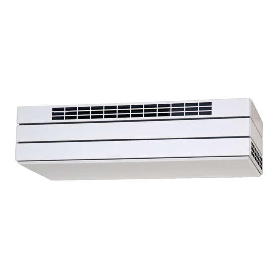
2. Description The X-Vent II 300 is a ventilation unit with air diffusion and extraction ventilators, filters in diffusion and exhaust, countercurrent heat exchangers and compact electronic control. The unit is designed for installation in the room to be ventilated. Ducts for supply and exhaust air are connected either to the back of the unit and lead out through the wall, or to the top of the unit and out through the roof. -
Page 5: Basic Circuit Diagram
Pressure tap for air volume measurement, exhaust Extract opening right side Inlet opening in front Power hook-up on right side Power hook-up on mounting plate for main box Main box Post-heating surface (optional) Inlet temperature sensor Condensate Pump (optional) CODUME Page 5... -
Page 6: Structure
2.6 Structure The unit seen from below, without service cover. CODUME Page 6... -
Page 7: Mechanical Installation
If the exhaust end is facing out towards glass panes, that distance must be greater. If these minimum distances are not observed, there is a risk of increased noise from the unit. Simplified picture illustrating mounting of unit on wall frame. CODUME Page 7... -
Page 8: Mounting Unit In Wall Frame
The duct size is Ø200mm. The recommended hole diameter is Ø210-215 mm, so the pipes can be insulated subsequently. Horizontally measure and mark distance down to centre of supply/exhaust, and mark centre in vertical direction. CODUME Page 8... - Page 9 The unit is on the underlay and is safely and securely placed on the lift. In the picture on the right, the unit is raised and can now be adjusted to the two guide hooks placed on the wall frame. CODUME Page 9...
- Page 10 Use a no. 13 screw wrench. The unit must hang horizontally; therefore, it is important to check and readjust. CODUME Page 10...
- Page 11 L = Phase brown 0 = Blue AC = Connection of cooling module (optional) Terminal block X3 Display panel attached. The unit is now hung, and the factory-supplied panels can be clicked onto the mounted clips. CODUME Page 11...
-
Page 12: Mounting Pipes And Grates
RETURN 3/6” (DN 10) FORWARD 3/6” (DN 10) AIRFLOW Water heating surface IT/FS: Temperature and flow sensor Valve housing with presetting N Thermo motor Valve housing with presetting 6 Thermostatic heat-retaining valve Air escape valve Shutoff valve (not Airmaster delivery) CODUME Page 12... - Page 13 20 °C and 101.3 kPa: Q = 0.34 ⋅ ⋅ ⋅ ⋅ q ⋅ ⋅ ⋅ ⋅ (IT – t) [ W ] where air volume in m desired supply temperature t = 15.9 °C temperature prior to post-heating surface CODUME Page 13...
- Page 14 Calculation of water volume The flow-through volume of water is calculated at 20 °C and 1 bar: [ L / h ] ⋅ − where heating needs water temperature forward water temperature return CODUME Page 14...
-
Page 15: Connecting The Electric Heating Surface
1 ~ 230 V + N + PE / 50 Hz 1 ~ 230 V + N + PE / 50 Hz Output: 78 W 1500 W Full-load power: 0.6 A 6.5 A * Connecting terminals: 0.75 mm 0.75 mm Max. fuse: 20 A 20 A CODUME Page 15... -
Page 16: Connecting The Display Panel
Connect (PIR) type ”Scantronic 420” movement sensors to the control box as instructed in the electrical diagram, page 23. On installation, refer to the instructions accompanying the PIR sensor (Sensor of movement). For configuration of the control, see the guide X-Vent Controller – functionalities and menu overview. CODUME Page 16... -
Page 17: External Connections
Terminate the screen at the main box, as shown in section 4.6 4.5 External connections Make external connections as shown in the following diagram. Manual start Terminate the screen as shown in section 4.6 4.6 Screen termination CODUME Page 17... - Page 18 Terminal block Bend screen and place under clamps, then tighten screws. Note: The screen is not terminated at the display and external sensors. Display connection CODUME Page 18...
-
Page 19: Appendix
5. Appendix 5.1 Main dimensions X-Vent II 300 WALL MODEL A = Bottom B = Inlet side C = Left side D = Right side E = Back side 1 = Exhaust 2 = Intake 3 = Inlet 4 = Extract... -
Page 20: Main Dimensions X-Vent Ii 300 Wall Model Partially Integrated
5.2 Main dimensions X-Vent II 300 WALL MODEL partially integrated A = Bottom B = Inlet side C = Left side D = Right side E = Back side 1 = Exhaust 2 = Intake 3 = Inlet 4 = Extract... -
Page 21: Ent Ii 300 Wall Model Combi 3
5.3 Main dimensions X-Vent II 300 WALL MODEL combi 3 A = Bottom B = Inlet side C = Left side D = Right side E = Back side 1 = Exhaust 2 = Intake 3 = Inlet 4 = Extract... -
Page 22: Main Dimensions X-Vent Ii 300 Roof Model Partially Integrated
5.4 Main dimensions X-Vent II 300 ROOF MODEL partially integrated A = Bottom B = Inlet side C = Left side D = Right side E = Back side 1 = Exhaust 2 = Intake 3 = Inlet 4 = Extract... -
Page 23: Electrical Diagram
24 VAC- (*1) CTS start (*1) See section “4.3.5 External connections” CTS flow (*1) See section ”4.3.5 External connections” X3-12 0-10V signal input X3-13 Condensed terminal 1 Alarm (*1) See section ”4.3.5 External connections” X3-14 Condensed terminal 2 CODUME Page 23... -
Page 24: Capacity Data
5.6 Capacity data Operation/Capacity at 35 dbA Operation/Capacity at 30 dbA CODUME Page 24... - Page 25 CODUME Page 25...
-
Page 26: On-Site Testing Of Air Volumes
5.7 On-site testing of air volumes CODUME Page 26... -
Page 27: Eu Declaration Of Conformity
Inlet air: Right side at the back. Exhaust air: Left side at the back. Air volume measured on pressure taps. WALL MODEL Inlet air Exhaust air ROOF MODEL Inlet air Exhaust air 5.9 EU declaration of conformity CODUME Page 27... - Page 28 Product X-Vent II 300 Is compliant with the following directives: Directives The Machinery Directive 2006/42/EC The Low Voltage Directive (2006/95/EC) The EMC Directive (2004/108/EU) CODUME sa. www.codume.eu info@codume.eu Tel : +32 2 511 20 10 Fax : +32 2 511 23 59...
Need help?
Do you have a question about the X-Vent II 300 and is the answer not in the manual?
Questions and answers