Table of Contents
Advertisement
Quick Links
Download this manual
See also:
Instruction Manual
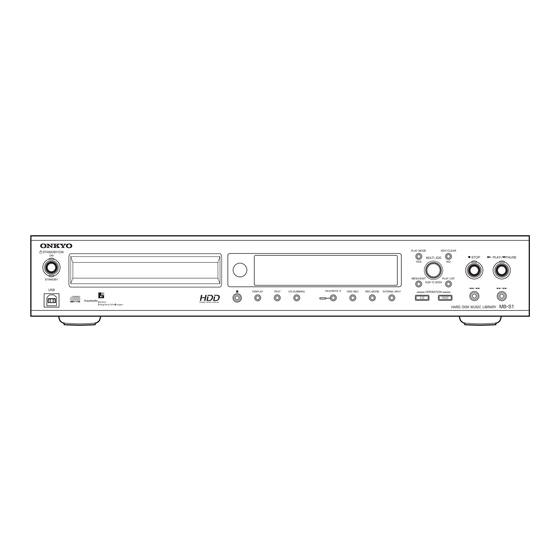
STANDBY/ON
ON
STANDBY
USB
Main microprocessor version
01X04b
UDD
~#400
UUP
~#400
01X23A
Apply
UDD
#401~
UUP
#401~
SERVICE MANUAL
SERVICE MANUAL
Hard Disk Music Library
MB-S1
MODEL
DISPLAY
TEXT
CD DUBBING
Black, Silver and Titanium models
BUDD
120V AC, 60Hz
TUUP,SUUT
120-240V AC, 50/60Hz
SAFETY-RELATED COMPONENT
WARNING!!
COMPONENTS IDENTIFIED BY MARK
SCHEMATIC DIAGRAM AND IN THE PARTS LIST ARE
CRITICAL FOR RISK OF FIRE AND ELECTRIC SHOCK.
REPLACE THESE COMPONENTS WITH ONKYO
PARTS WHOSE PART NUMBERS APPEAR AS SHOWN
IN THIS MANUAL.
MAKE LEAKAGE-CURRENT OR RESISTANCE
MEASUREMENTS TO DETERMINE THAT EXPOSED
PARTS ARE ACCEPTABLY INSULATED FROM THE
SUPPLY CIRCUIT BEFORE RETURNING THE
APPLIANCE TO THE CUSTOMER.
PLAY MODE
EDIT/CLEAR
STOP
PLAY
/
PAUSE
MULTI JOG
YES
NO
MENU/EXIT
PLAY LIST
PUSH TO ENTER
FAVORITE IT
HDD REC
REC MODE
EXTERNAL INPUT
OPERATION
C D
HDD
MB-S
1
HARD DISK MUSIC LIBRARY
ON THE
MB-S1
Ref. No. 3710
112001
Advertisement
Table of Contents

Related Manuals for Onkyo MB-S1


Summary of Contents for Onkyo MB-S1
- Page 1 COMPONENTS IDENTIFIED BY MARK ON THE SCHEMATIC DIAGRAM AND IN THE PARTS LIST ARE CRITICAL FOR RISK OF FIRE AND ELECTRIC SHOCK. REPLACE THESE COMPONENTS WITH ONKYO Main microprocessor version PARTS WHOSE PART NUMBERS APPEAR AS SHOWN IN THIS MANUAL.
-
Page 2: Specifications
MB-S1 Specifications CD-ROM Drive Unit ATA Packet Interface (specified in SFF-8020). (E-IDE) Industry Standard 3.5" Half Height Form Factor. Hard Disk Drive Unit AT Attachment 5 (ATA-5) Industry Standard 5.25" Half Height Form Factor. 40GB D/A Converter Single bit (Crystal CS4341, 24bit/96kHz) -
Page 3: Service Note
DESCRIPTION F9001 252160 FUSE, 2.5A-UL/T-237 <D> "HDD Check 999" 252076 FUSE, 3.15A-SE-EAK <T,P> System error occurred. Do not operate the MB-S1 until the count down is over. Note: <D>: 120V model only <P>: European model only "HDD Media Full" <T>: Asian model only The HDD is full. - Page 4 MB-S1 MICROPROCESSOR TERMINAL DESCRIPTION Q7502: MPD780232GC-052-8BT PIN NO. FUNCTION LOGIC DESCRIPTION INIT ACTIVE SLEEP P-OFF Vdd1 + 5V power supply Vss1 Main clock (5MHz) input terminal Main clock (5MHz) input terminal RESET microprocessor reset terminal SUBCL/SCK Main microprocessor communication and a flash write-in clock input combination terminal...
- Page 5 (intact) (Up (H)) PRVSW1 Destination distinction switch 1 (temporary) PRVSW2 Destination distinction switch 2 (temporary) Model distinction switch (L:MB-S1 H:HDR -1) General-purpose switch 2 (main program forcible download switch) General-purpose switch 3 (for an external ROM/RAM check) 80-85 (intact) (Up (H)) "The terminal for power failure detection (it will input, by the time it will fall completely, if voltage begins to fall) "...
- Page 6 MB-S1 The test menu operation method - 1 <How to a test menu (level 2) to enter> <DOWNLOAD START functional details> 1. Change unit into a standby mode. [Methode] 2. Push the DISPLAY key and the STOP key simultaneously. 1. Choose a menu as "DOWNLOAD START" and push JOG.
- Page 7 MB-S1 The test menu operation method - 2 <VERSION functional details> [Real whereabouts method] 1. Combine a menu with "VERSION" and push JOG. 2. The version of each farm is displayed. A display can be changed by turning JOG. The contents displayed are as follows.
-
Page 8: Exploded View
MB-S1 EXPLODED VIEW A34<D> A35<T,P> A34<D> A35<T,P> A34<D> F9001 A35<T,P> A34<D> A35<T,P>... -
Page 9: Exploded Views - Parts List
<P> COMPONENTS IDENTIFIED BY MARK ARE CRITICAL FOR REAR PANEL 27122920 <D> RISK OF FIRE AND ELECTRIC SHOCK. 27122919 <T,P> REPLACE THESE COMPONENTS WITH ONKYO PARTS BOTTOM LEG(AS) 27175388 WHOSE PART NUMBERS APPEAR AS SHOWN IN THIS CUSHION(SHLD) 28141490 MANUAL. - Page 10 MB-S1 SCHEMATIC DIAGRAM (NAAR-7346) -1 L 4 5 0 2 R 4 5 2 7 R 4 5 1 1 R 4 5 1 8 Q 4 5 0 1 B L M 2 1 P 2 2 1 S G...
- Page 11 MB-S1 SCHEMATIC DIAGRAM (NAAR-7346) -2 N A A R - 7 3 4 6 C 4 0 2 3 R 4 0 2 7 8 2 0 4 7 2 C 4 0 0 3 C 4 0 1 7...
- Page 12 MB-S1 SCHEMATIC DIAGRAM (NAAR-7346) -3 N A A R - 7 3 4 6 N A D I S - 7 3 4 9 C 7 0 2 4 1 0 4 Z A 1 6 A 1 7 A 1 5...
- Page 13 MB-S1 SCHEMATIC DIAGRAM (NAAR-7346) -4 N A D I S - 7 3 4 9 Q 7 5 0 3 B J 8 4 3 G N K F L F + F L F - F L F -...
- Page 14 MB-S1 SCHEMATIC DIAGRAM (NAPS-7350:<D>) -1 N A P S - 7 3 5 0 L 9 0 L 9 0 T 9 0 0 1 S T - 5 1 0 B - 1 R 9 0 0 1 D 9 0 1 0 R 9 0 1 1 0 .
- Page 15 MB-S1 SCHEMATIC DIAGRAM (NAPS-7350:<D>) -2 L 9 0 0 3 H 1 2 V H 1 2 V G N D Q 9 0 0 3 S I - 3 1 2 0 C 1 0 0 K + 1 2 V...
- Page 16 MB-S1 SCHEMATIC DIAGRAM (NAPS-7350:<T,P>) -1 N A P S - 7 3 5 0 T 9 0 0 1 S T - 5 1 0 B - 1 R 9 0 0 1 D 9 0 1 0 R 9 0 1 1 0 .
- Page 17 MB-S1 SCHEMATIC DIAGRAM (NAPS-7350:<T,P>) -2 L 9 0 0 3 H 1 2 V H 1 2 V G N D Q 9 0 0 3 S I - 3 1 2 0 C 1 0 0 K + 1 2 V...
-
Page 18: Packing View
29365083B <D> REMOTE CONTROL UNIT, RC-459P 24140459 BATTERY,UM-3 3010054 PIN-CORD AS or 2010098A or PIN CORD AS 2010326 CORD AS (RI) 2010200 CD-ROM (MB-S1) 292174A CORD AS (USB-1M) 2010391 CV PLUG,CV-K-2 25055911 <T> INS MANUAL,E(MB-S1) 29343221A INS MANUAL,Ct(MB-S1) 29343223 <T>... - Page 19 MB-S1 PC BOARD VIEW - 5 U5:NAPS-7350 (Bottom Side View from Top Side) D9025 C9039 C9038 U5:NAPS-7350 (Top Side View from Bottom Side) L9003 2.5A/125V P9002 E9001 NCPS-7350 D9018 25137350 L9003 J9021 F9011 F9001 F9012 C9011 C9012 FIRE RISK J9022...
- Page 20 MB-S1 PC BOARD VIEW - 4 U4:NADIS-7349 (Bottom Side View from Top Side) Q7503 EDIT_NO PLAY_MODE NCDIS-7349 S7501 25137349F Q7503 D7510 D7509 C7505 S7502 S7507 C7510 S7501 PLAY STOP S7513 S7510 C7507 PLAYLIST_YES MENU_EXIT S7519 S7518 Q7513 J766 J760 J753...
- Page 21 MB-S1 PC BOARD VIEW - 3 U2:NAETC-7347 (Top Side View from Bottom Side) P7013 P7011 P7018 NCETC-7347 P7013 E7001 25137347 L7003 C7070 C7079 P7018 P7011 C7073 C7080 L7002 R7094 P7017 R7093 C7072 C7071 U3:NAETC-7348 (Top Side View from Bottom Side)
- Page 22 MB-S1 PC BOARD VIEW - 2 U1:NAAR-7346 (Bottom Side View from Top Side)
- Page 23 MB-S1 PC BOARD VIEW - 1 U1:NAAR-7346 (Top Side View from Bottom Side) Q3002 Q3003 P4201 P4101 P3003 P3002 Q3005 Q3002 C3004 C4206 C4205 R3004 R4206 R4205 Q3004 C3012 R4207 Q4506 C3005 Q3001 Q4603 E4307 R4208 R7137 R4107 C4106 C4105...
-
Page 24: Printed Circuit Board Parts List
MB-S1 PRINTED CIRCUIT BOARD PARTS LIST-1 NAAR-7346 C-No Description Part number C-No Description Part number [RESISTOR] [SEMI CONDUCTOR] R7108 RESISTOR,miniSMDC100 4000192R2 D4601,D4602, C-DIODE,1SS352 223234R2 [SW TRM] D4603 E4302 TRM(SCREW), D7001 ZENER D,UDZS5.1B 224550510R2 NEGITANSI M3 25065425 D7002,D7003 C-DIODE,1SS352 223234R2 E4303-E4306... - Page 25 R9008 METAL O R,RS2WBJ-47K 441724734F CAL FOR RISK OF FIRE AND ELECTRIC SHOCK. R9009 METAL O R,RS1/2WBJ-1K 443521024 REPLACE THESE COMPONENTS WITH ONKYO PARTS R9010 METAL O R,RS1/2WBJ-47 443524704 WHOSE PART NUMBERS APPEAR AS SHOWN IN THIS R9011,R9012 METAL R,RNU1/2WCJ-1 453530104 MANUAL.
- Page 26 Sales & Product Planning Div. : 2-1, Nisshin-cho, Neyagawa-shi, OSAKA 572-8540, JAPAN Tel: 072-831-8111 Fax: 072-833-5222 ONKYO U.S.A. CORPORATION 18 Park Way, Upper Saddle River, N.J. 07458, U.S.A. Tel: 201-785-2600 Fax: 201-785-2650 E-mail: onkyo@onkyousa.com ONKYO EUROPE ELECTRONICS GmbH Industriestrasse 20, 82110 Germering, GERMANY Tel: 089-849-320 Fax: 089-849-3265 E-mail: info@onkyo.de...
Need help?
Do you have a question about the MB-S1 and is the answer not in the manual?
Questions and answers