
Summary of Contents for General Instrument C6M-II
- Page 1 C6M-II ® Commander 6 Modulator Installation Manual TEST REF OFF video modulation (%) -20dB VIDEO C6M-II VIDEO OFF 87.5 VIDEO B AUX IF PRGM IF audio deviation (kHz) REMOTE...
- Page 2 General Instrument. General Instrument reserves the right to revise this publication and to make changes in content from time to time without obligation on the part of General Instrument to provide notification of such revision or change.
-
Page 3: Table Of Contents
Section 2 Overview Options ........................C6M-II-MOB Kit ...................... C6-DC ........................C6-RC-II Kit ......................C6M-II-SE Kit ......................Model Conventions ..................... Front Panel Controls and Displays ................Rear Panel Connectors ....................The Menu System ......................Using the Menus ..................... Changing a Menu Item .................... - Page 4 Composite Baseband Interfacing ................3-12 CMTS / MVP II / C6M-II Connections ..............3-13 C6R-VCII / CMTS / MVP II / C6M-II Connections ............. 3-14 Section 4 System Block Diagrams Video to IF Modulation System ................... Audio to IF Modulation System ..................
- Page 5 External composite baseband connection ............ 3-12 Figure 3-10 C6M-II / MVP II / CMTS interfacing ............. 3-13 Figure 3-11 C6R-VCII / CMTS / MVP II / C6M-II connections ......... 3-14 Figure 4-1 Video to IF modulation system ..............Figure 4-2 Audio to IF modulation system ..............
-
Page 6: Section 1 Introduction
Section 1 Introduction The C6M-II is a state-of-the-art television signal modulator for the most demanding CATV applications. The system is packaged in a space saving 1.75-inch high rack-mounted housing and uses efficient switching power supply regulators to minimize power consumption and heat. -
Page 7: Using This Manual
Although these documents provide information that may be of interest to you, they are not necessary to install or operate the C6M-II modulator. Document Conventions Before you begin using the C6M-II, familiarize yourself with the stylistic conventions used in this manual: Denotes silk screening on the equipment, typically representing front and rear-panel SMALL CAPS controls, I/O connections and indicators (LEDs). -
Page 8: If You Need Help
Introduction If You Need Help If you need assistance while working with the C6M-II, call the General Instrument Technical Response Center at 1-888-GEN-INST (1-888-436-4678). The Technical Response Center is open from 8:00 a.m. to 9:00 p.m. Eastern Time, Monday through Friday. When the Technical Response Center is closed, emergency service only is available on a call-back basis. -
Page 9: Section 2 Overview
Section 2 Overview The C6M-II is a frequency agile modulator offering an output frequency range from 50 MHz to 1 GHz. All standard, HRC, IRC, and EIA frequencies are available either by keying in the frequency or using the convenient channel maps. -
Page 10: C6M-Ii-Mob Kit
RS-485 type interface using RJ-12 connectors. C6M-II-SE Kit The C6M-II-SE is a stereo encoder option for generating stereo sound. It encodes baseband audio based on BTSC standards, and employs dbx-TV noise reduction circuitry to ensure a quality signal. This option does not have Second Audio Program (SAP). For SAP applications, the CMTS should be used. -
Page 11: Model Conventions
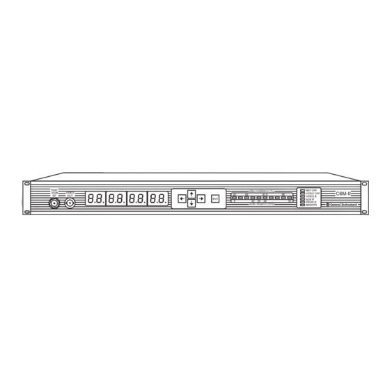
Front Panel Controls and Displays The front panel of the C6M-II modulator, which includes an operational display, test ports, a keypad for adjustments, a bar graph and a status display, is illustrated in Figure 2-1. Figure 2-1 C6M-II front panel The following table describes the function of each item on the C6M-II front panel. - Page 12 BNC type coaxial connector. The eight-digit alphanumeric LED display shows all functions and controls used to operate the C6M-II. The keypad with four arrow push buttons is used to navigate through the menus. When the desired menu item is reached, the right arrow key is used to access the functions.
-
Page 13: Rear Panel Connectors
Overview Rear Panel Connectors The rear panel of the C6M-II modulator with options installed is illustrated in Figure 2-2. Figure 2-2 C6M-II rear panel with options installed Note: All external jumpers take precedenc e over menu selection. This includes AUX IF, VIDEO B, SUBCARRIER, and PRGM IF. - Page 14 Overview The following table describes the features on the rear panel of the C6M-II modulator. Table 2-3 Description of rear panel connections Feature Description Power line connector. Label indicates input power range. connectors are used to apply comb generator REF OUT REF IN reference signals for phase-locked operation.
- Page 15 VIDEO B terminal on the rear panel. will be activated in when VIDEO IN B loss of video is detected on if this feature is enabled VIDEO IN A through the menu. These are BNC type coaxial connectors. C6M-II Installation Manual...
-
Page 16: The Menu System
Overview The Menu System The C6M-II is operated by menus which are accessed by the four push buttons and the located on the front panel. The relationship of the menus is shown graphically in Figure 2 -3. Figure 2-3 Menu relationships... -
Page 17: Using The Menus
If you take no action, the flashing value will revert to the previous value after a short delay. See Appendix C, Changing a Menu Item for a step-by-step description of how to change a menu item. C6M-II Installation Manual... -
Page 18: Main Menu
Video Menu Provides access to the video menu. Press the right arrow key to enter the video menu. Audio Menu Provides access to the audio menu. Press the right arrow key to enter the audio menu. C6M-II Installation Manual... -
Page 19: Option Menu
Automatic Gain Toggles IF AGC between ON (IAGC ON) and OFF Control (IF AGC) (IAGC OFF) For normal operation, it should be on. Manual Gain Control If IF AGC is turned off, MGC is available. (IF MGC) C6M-II Installation Manual... - Page 20 Displays the first seven characters of the unit remote control address. The address is same as the serial number. Address is factory programmed and cannot be changed. Address Low Displays the last six characters of the unit remote control address. C6M-II Installation Manual...
-
Page 21: Video Menu
Toggles between two different input impedance. LOW indicates a 600 ohm balanced. HI indicates greater than 15 kohms. When the stereo encoder option is in operation, it is set to HI, displays MTS, and cannot be changed. C6M-II Installation Manual... -
Page 22: Remote Menu
Toggles between ON and OFF. It must be ON for remote operation. When turned ON, operating parameters cannot be changed locally. Baud rate Displays communication rate. This parameter cannot be changed. Remote type Displays the remote control type. This parameter cannot be changed. C6M-II Installation Manual... -
Page 23: Warning Messages
REAR PAN Attempt to change the input source while it is selected through the rear panel terminal block. Input selection by the terminal block has the highest priority. See Appendix D, Signal Priority Chart . C6M-II Installation Manual... -
Page 24: Section 3 Installation
Provided as spares parts for the terminal block. If you are installing the C6M-II in a system that currently has a C6M and will operate in a range higher than 600 MHz, an external lowpass filter, model C6-LPF600 (928-363-000) or equivalent should be included. -
Page 25: Checking The Operation
Plug the unit into an appropriate power line and allow it to warm up for five minutes. Check that the indicators glow steadily. VIDEO OFF REF OFF Connect a standard baseband video signal generator to the connector on the rear VIDEO IN A " panel. C6M-II Installation Manual... -
Page 26: Switching Capabilities
VIDEO A AUX IF via menu. When the video signal returns and the C6M-II detects its presence, it will switch back to the . To activate this feature, select AUXA ON from the Option menu. VIDEO A... -
Page 27: Automatic Gain Control
To activate this feature, select PGMA ON from the Option menu. When the video signal to video A is missing, the C6M-II automatically switches to video B as the backup source. If video B is also missing, the unit can switch to . -
Page 28: Audio Parameters
Channels 54, 55 and 56 are at the IRC frequencies. Channels 42, 60 and 61 have the + 25 kHz FCC frequency offsets built in. The C6M-II has the capability to output any frequency in increments of 12.5 kHz if needed. If and/or is used in HRC, IF frequency must be 45.7522875 MHz. -
Page 29: Typical Interconnections
Installation Typical Interconnections Basic Video and Audio Interfacing Figure 3-3 shows the standard connections for a video and audio input, and RF output. Figure 3-3 Basic video/audio interfacing C6M-II Installation Manual... -
Page 30: Satellite Link Connection
Installation Satellite Link Connection Figure 3-4 shows the connection between the C6R-VCII satellite receiver and the C6M-II. Figure 3-4 Satellite link connection C6M-II Installation Manual... -
Page 31: Satellite Link Connection With C6M-Ii-Se
Installation Satellite Link Connection with C6M-II-SE Figure 3-5 shows the connection between the C6R-VCII satellite receiver and the C6M-II with the Stereo Encoder option installed. Figure 3-5 Satellite link connection with stereo encoder C6M-II Installation Manual... -
Page 32: Video Scrambling
Measure the RF output and check for the following conditions: If the RF video carrier output is less than 60 dBmV, adjust the RF output on the C6M-II for 60 dBmV. Deactivate the IF AGC on the Option menu display and select auxiliary IF (INPT AUX) on the Main menu as the input. -
Page 33: Cw Output
The CW output is a 45.75 MHz carrier signal that can be used with the MVP II when it is necessary to insert a coherent IF carrier for phase-locked upconversions. Figure 3-7 illustrates the connection of the C6M-II and the MVP II in a phase-locked upconversion. -
Page 34: Stereo If Interfacing
3-11 Stereo IF Interfacing The CMTS stereo encoder can be used with the C6M-II as shown in Figure 3-7 if the MOB option board is installed. To activate the subcarrier input, select the Input selection menu item INPT SUB on the Main menu or short the subcarrier terminal on the rear panel to the ground terminal. -
Page 35: Composite Baseband Interfacing
Menu selection is recommended. The short on the rear panel is not required if the INPT CMP option is selected via the menu. Figure 3-9 External composite baseband connection C6M-II Installation Manual... -
Page 36: Cmts / Mvp Ii / C6M-Ii Connections
Installation 3-13 CMTS / MVP II / C6M-II Connections Figure 3-10 shows the connections between the CMTS, MVP II and C6M-II. Figure 3-10 C6M-II / MVP II / CMTS interfacing C6M-II Installation Manual... -
Page 37: C6R-Vcii / Cmts / Mvp Ii / C6M-Ii Connections
3-14 Installation C6R-VCII / CMTS / MVP II / C6M-II Connections Figure 3-11 shows the connections between the C6R-VCII, CMTS, MVP II and C6M-II. Figure 3-11 C6R-VCII / CMTS / MVP II / C6M-II connections C6M-II Installation Manual... -
Page 38: Section 4 System Block Diagrams
Section 4 System Block Diagrams This section describes the operation of the C6M-II through a series of block diagrams. The text is keyed to letters on the block diagrams. Video to IF Modulation System Figure 4-1 Video to IF modulation system If the modulator option board is installed, baseband video input switching is available. -
Page 39: Audio To If Modulation System
(VCO). The center frequency of the sound carrier is precisely maintained by a phase-locked loop with an internal 2.0 MHz reference. The audio VCO’s frequency is divided by two to produce the standard 4.5 MHz aural subcarrier C6M-II Installation Manual... - Page 40 The subcarrier is mixed with the unmodulated 45.75 MHz signal to create the 41.25 MHz sound IF frequency. The sound IF carrier is bandpass filtered and applied to an amplifier whose gain is controlled by the A/V separation entry on the Main menu. This control sets the desired picture/sound carrier level ratio. C6M-II Installation Manual...
-
Page 41: If Switching And Agc System
A sample of that signal is provided at a front panel test point at 0 dBmV. With the option package installed, an additional relay is provided. The switch takes its two inputs inputs and delivers its output to the second input of the first from the rear panel PRGM relay switch. C6M-II Installation Manual... -
Page 42: If To Channel Converter System
20 dB below actual is brought to a front panel connector for monitoring the final output signal. The RF signal is amplified by a wideband low distortion amplifier module to provide the 60 dBmV specified picture carrier output level. C6M-II Installation Manual... -
Page 43: Appendix A Specifications
41.25 MHz Sound IF Output Level 15 to 25 dBmV CW IF Output Frequency 45.75 MHz 50 dBmV ±5 dB CW IF Output Level 30 dBmV ±1 dB @ 87.5% modulation Composite IF Output (picture IF level) Video C6M-II Installation Manual... -
Page 44: Audio
+35 to 45 dBmV General ac Voltage Requirements 100 to 240 Vrms, 50 to 60 Hz Power Requirements 40 watts maximum Operating Temperature 0 to 50° C Weight 13.5 lbs maximum Dimensions 19” W x 1.75” H x 17.5” D C6M-II Installation Manual... -
Page 45: Appendix B Frequency Plan
145.2500 150.0075 151.2625 151.2500 151.2500 156.0078 157.2625 157.2500 157.2500 162.0081 163.2625 163.2500 163.2500 168.0084 169.2625 169.2500 169.2500 216.0108 217.2625 217.2500 217.2500 222.0111 223.2625 223.2500 223.2500 228.0114 229.2625 229.2625 229.2625 234.0117 235.2625 235.2625 235.2625 240.0120 241.2625 241.2625 241.2625 C6M-II Installation Manual... - Page 46 372.0186 373.2625 373.2625 373.2625 378.0189 379.2625 379.2625 379.2625 384.0192 385.2625 385.2625 385.2625 390.0195 391.2625 391.2625 391.2625 396.0198 397.2625 397.2625 397.2625 72.0036 73.2625 73.2500 78.0039 79.2625 79.2500 84.0042 85.2625 85.2500 90.0045 91.2625 91.2500 91.2500 96.0048 97.2625 97.2500 97.2500 C6M-II Installation Manual...
- Page 47 511.2500 516.0258 517.2625 517.2500 517.2500 522.0261 523.2625 523.2500 523.2500 528.0264 529.2625 529.2500 529.2500 534.0267 535.2625 535.2500 535.2500 540.0270 541.2625 541.2500 541.2500 546.0273 547.2625 547.2500 547.2500 552.0276 553.2625 553.2500 553.2500 558.0279 559.2625 559.2500 559.2500 564.0282 565.2625 565.2500 565.2500 C6M-II Installation Manual...
- Page 48 697.2500 702.0351 703.2625 703.2500 703.2500 708.0354 709.2625 709.2500 709.2500 714.0357 715.2625 715.2500 715.2500 720.0360 721.2625 721.2500 721.2500 726.0363 727.2625 727.2500 727.2500 732.0366 733.2625 733.2500 733.2500 738.0369 739.2625 739.2500 739.2500 744.0372 745.2625 745.2500 745.2500 750.0375 751.2625 751.2500 751.2500 C6M-II Installation Manual...
- Page 49 883.2500 888.0444 889.2625 889.2500 889.2500 894.0447 895.2625 895.2500 895.2500 900.0450 901.2625 901.2500 901.2500 906.0453 907.2625 907.2500 907.2500 912.0456 913.2625 913.2500 913.2500 918.0459 919.2625 919.2500 919.2500 924.0462 925.2625 925.2500 925.2500 930.0465 931.2625 931.2500 931.2500 936.0468 937.2625 937.2500 937.2500 C6M-II Installation Manual...
- Page 50 943.2500 948.0474 949.2625 949.2500 949.2500 954.0477 955.2625 955.2500 955.2500 960.0480 961.2625 961.2500 961.2500 966.0483 967.2625 967.2500 967.2500 972.0486 973.2625 973.2500 973.2500 978.0489 979.2625 979.2500 979.2500 984.0492 985.2625 985.2500 985.2500 990.0495 991.2625 991.2500 991.2500 996.0498 997.2625 997.2500 997.2500 C6M-II Installation Manual...
-
Page 51: Appendix C Changing A Menu Item
If this is the change you want, press the key to implement the change. If you decide not to make the change, do not press . The frequency will return to the previous value after a short delay. C6M-II Installation Manual... - Page 52 Press the key to implement a change. Use the left arrow key to exit the menu. If no change is made, the value reverts to the previous setting. C6M-II Installation Manual...
-
Page 53: Appendix D Signal Priority Chart
Appendix D Signal Priority Chart C6M-II Installation Manual... - Page 54 Signal Priority Chart C6M-II Installation Manual...
- Page 55 Signal Priority Chart C6M-II Installation Manual...
- Page 56 Signal Priority Chart C6M-II Installation Manual...
- Page 57 Signal Priority Chart C6M-II Installation Manual...
-
Page 58: C6-Lpf600
The C6-LPF600 (GI Part No. 928-363-000) is installed either at the RF output of the C6M, or may be installed at the C6M RF combined output before the insertion of channels operating above 600 MHz. Typical installations with the C6M and the C6M-II are displayed below. Figure E-1 Typical installations of C6-LPF600... -
Page 59: Specifications
Application Notes Specifications Passband Stopband Bandwidth 10 to 600 MHz 600 to 1000 MHz Insertion Loss 2.0 dB maximum –40 dB minimum @ 673 MHz Return Loss –14 dB minimum C6M-II Installation Manual... - Page 60 General Instrument Corporation GI Communications Division Printed in U.S.A. 410515-001-99, 3/97...
Need help?
Do you have a question about the C6M-II and is the answer not in the manual?
Questions and answers