Table of Contents
Advertisement
Advertisement
Table of Contents

Summary of Contents for ANTlabs InnGate 3 M-series
- Page 1 ATE 3 DMINISTRATOR’S ANUAL OCUMENT ELEASE 1.01...
- Page 2 InnGate 3 Administrator’s Manual This manual provides an in-depth coverage of the setup, configuration and administration of an InnGate 3 and is intended for system and network administrators who will be performing these tasks. Copyright © 2002 - 2009 Advanced Network Technology Laboratories Pte Ltd. All rights reserved.
- Page 3 TRADEMARKS AND ACKNOWLEDGEMENTS The following trademarks and acknowledgments apply to the following: The InnGate system and Tru’Connect™ technology are products and technologies of Advanced Network Technology Laboratories Pte Ltd, labs (ANT ). Windows and Microsoft are registered trademarks of Microsoft Corporation. Solaris is a registered trademark of Sun Microsystems.
-
Page 4: Table Of Contents
CONTENTS Chapter 1 ....................9 GETTING STARTED ................9 Overview ................9 1.1.1 Hardware ................. 10 1.1.2 Network Operation............11 Recommended Setting ............12 System Setup ................ 12 1.3.1 Accessing the Web-based Admin GUI ......... - Page 5 Device Detection Setup ............75 ARP Setup ................76 Chapter 4 ....................78 WAN NETWORK SETTINGS ..............78 Overview ................78 WAN Setup ................78 4.2.1 Defining a Static Route ............78 ...
- Page 6 Powering up and shutting down the system ......113 System Configuration Backup or Restore ....... 114 Applying System Patches ............115 Setting the Date and Time ............ 116 Syslog Configuration ............117 ...
- Page 7 Appendix D ..................156 UPLOADING CUSTOM WEBPAGES ............. 156 Appendix E ................... 157 CUSTOM SSL LOGIN PAGES .............. 157 Appendix F ................... 161 ERROR PAGES ................. 161 Appendix G ..................163 CREDIT CARD .................. 163 ...
- Page 8 Department Document Reference No. E-Mail Comments/Feedback Also, please include the chapter, section and/or page number when referring to specific portions of the document. Send your comments via email to documentation@antlabs.com Page 8 of 164 Connectivity Made Easy...
-
Page 9: Chapter 1
Chapter 1 GETTING STARTED Overview This chapter will illustrate a simple network deployment of the InnGate 3 involving the following 3 steps: 1. System Setup – Configuring the InnGate to operate in the network. 2. Network Installation – Connecting the InnGate to the network. 3. -
Page 10: Hardware
Although your own network will likely differ from this, the general principles for installing and configuring the InnGate are still applicable. The setup covered in this chapter is suitable for quick demonstrations and small-scale setups. Later chapters will cover details for more complex deployment scenarios. -
Page 11: Network Operation
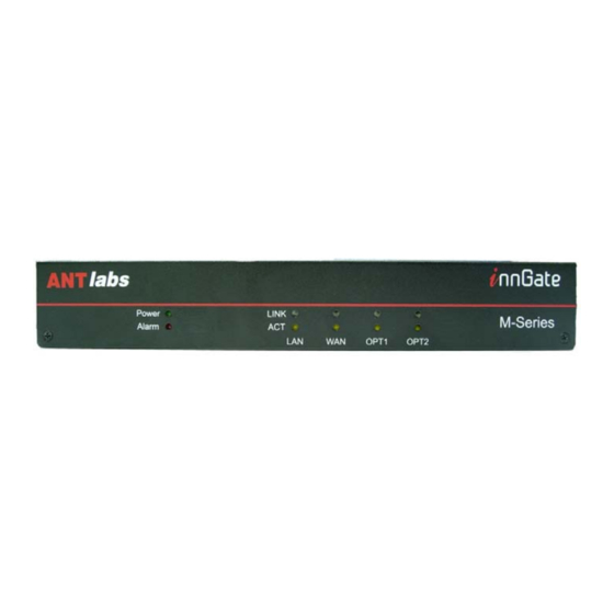
1. USB Serial Console – The left USB port allows direct console access to the InnGate. Use the provided USB-to-serial converter to connect a PC with a terminal program to access the console (see Section 8.12). 2. Serial Console – The M-series serial console allows direct console access to the InnGate. -
Page 12: Recommended Setting
When in operation, the InnGate performs Network Address and Port Translation (NAPT) on the WAN interface for downstream clients (routing can also be done and is discussed in Section 3.2 and Section 3.3). Thus when a downstream client wants to send packets to the upstream, the InnGate will do so using its WAN IP address. -
Page 13: Accessing The Web-Based Admin Gui
The URL to access the Admin GUI is: https://ezxcess.antlabs.com/admin/ The “ezxcess.antlabs.com” domain is only valid on the LAN network (assuming that LAN access to the Admin GUI is not blocked) and is not a valid domain on the public Internet. - Page 14 Figure 1-4 SSL Warning Message The administrator’s login page is presented next (see Figure 1-5). Figure 1-5 Login Prompt Login with the default User ID “ ” and default password “ ”. root admin It is recommended that you change the default password (see Section 8.3.2) to prevent unauthorized access.
-
Page 15: Configuring The Wan Interface
The various menu options are displayed on the left side of the page and you may return to the main Admin page at any time by clicking on the “InnGate” logo at the top-left corner of the browser window. 1.3.2 Configuring the WAN Interface The WAN interface has to be properly configured with a routable IP address, valid subnet mask and gateway in order for the InnGate to function correctly in your network. - Page 16 Figure 1-8 Modify WAN Profile The various fields are described as follows: 1. IP Address – The host IP address for the InnGate on the upstream network. The factory default IP address setting is . Change this to 192.168.0.1 a valid routable IP address on your upstream network. 2.
-
Page 17: Configuring The Domain Name Server
5. Source NAT Address Range – The InnGate will use the pool of IP addresses defined here when performing network address and port translation (NAPT) on the WAN interface for its downstream clients. The WAN IP address must be in the same subnet as the source NAT address range 6. -
Page 18: Configuring The Web Proxy
The InnGate comes with a default entry which we will modify according to your network DNS defined. Click on the entry to proceed. The DNS configuration page will be displayed (see Figure 1-10). Figure 1-10 DNS Configuration Page The fields are described here: 1. - Page 19 Figure 1-11 Web Proxy Configuration The various fields are described as follows: 1. Direct Connection – Select this if your network allows direct connections to the Internet. 2. Use Proxy – Select this if your network requires the use of a web proxy for browsing.
-
Page 20: Creating A Plan
1.3.5 Creating a Plan Next you need to create the different types of service plans required. This depends on your business needs. To configure the Plans: 1. Click on Policies. 2. Click on Plans. Any existing plans will be shown. Select an existing plan or create a new one. Figure 1-12 Plans Figure 1-13 shows the plan creation page. - Page 21 You need to purchase the Stored Volume Prepaid module in order for this option to be enabled. d. Stored Volume – multiple usage periods valid as long as there is balanced volume left. i. Change users to Throttled plan after volume is exceeded –...
-
Page 22: Firewall Rules
Figure 1-13 Creating a Plan Click to confirm the changes. 1.3.6 Firewall Rules The InnGate allows you to define firewall-like rules that can be applied to individual User Groups for greater control over network access. To configure a Firewall rule: 1. - Page 23 The Firewall rule definition page will be displayed (see Figure 1-15). Figure 1-15 Plan Firewall The fields are described as follows: 1. Plan – The Plan that this firewall rule will apply to. You can also configure Firewall rules for the following default groups of devices: ...
-
Page 24: Creating A Location
b. No VLAN – Applies to traffic that has no VLAN tag. 4. Protocol – This specifies the type of network traffic that the firewall will pick up. 5. Source Network – The firewall will pick up network traffic originating from the specified IP address or network. - Page 25 After making a selection, details about the location is displayed (see Figure 1-17). Figure 1-17 Location Settings Creating a location is a multi-step process and the wizard will guide you through the steps. Figure 1-18 Pre-Login Page The Pre-Login section lets you configure what page is shown to the user instead of the login page.
- Page 26 When using a pre-login page, make sure it eventually sends the user to the welcome page to login. Figure 1-19 Welcome Page The Welcome Page section lets you configure how the welcome login page will look like. 1. Title – The title of the page shown in the browser. 2.
- Page 27 The next step in the wizard allows you to select the different access options available to users in this location you are creating: 1. Complimentary Access – This means the user will not be charged and there is no need to enter a User ID and Password. Select from the list of plans created previously.
- Page 28 Figure 1-23 PMS Authentication a. Display Label b. Authentication – When this option is checked the guest based authentication is enabled. Guest is required to specify the room number, guest name, or reservation number. If it is unchecked the room based authentication is enabled. c.
- Page 29 5. Access Code Authentication – Instead of a User ID and Password system, this only requires an access code to be entered for access. Figure 1-24 Access Code Authentication 6. Authentication Display – Define the order in the drop-down list of authentication options that is shown to the user.
- Page 30 Figure 1-27 Success Pages These are the fields: 1. Login / Logout Success Message – The messages shown to the user. 2. Display Logout Button – To show the button for logging out of the session. Useful for time duration based plans. 3.
- Page 31 Click to proceed with the next step in the wizard. The next step is to define what is shown to the user if the system encounters an error. Figure 1-28 Error Page Click to proceed with the next step in the wizard. The next step is to define what to name the various labels on the pages shown to the user in the whole authentication process.
-
Page 32: Creating Vlans
Figure 1-30 Error Page At any step in the wizard, you can always click to confirm the changes. 1.3.8 Creating VLANs Within each location, you will now assign VLANs to it so that under each VLAN you can have network specific controls. To configure the VLAN: 1. - Page 33 The fields are described as follows: 1. VLAN ID – Unique VLAN identifier. Must correspond to the VLAN setup in the switch connected via the trunk port. 2. Location – Select the Location that this VLAN belongs to. 3. Max. Logins/Sessions – The maximum number of concurrent users allowed on the VLAN.
-
Page 34: Importing And Exporting Vlan Definitions
A default entry treats traffic that is not VLAN tagged (“No VLAN”) to be assigned to the “Default” VLAN Group. You can change this treatment if required. 1.3.9 Importing and Exporting VLAN Definitions To import/export VLAN definitions: 1. Click on Locations. 2. -
Page 35: Network Installation
Errors will be highlighted by the system. The CSV file must provide these fields enclosed with double quotes, in the following order, separated by commas, and each entry on a separate line: 1. VLAN ID 2. Location 3. Max. Logins/Sessions 4. -
Page 36: Vlan-Enabled Networks
1.4.1 VLAN-enabled Networks When incorporating the InnGate in a VLAN-enabled network, the LAN interface must connect to an 802.1Q-enabled trunk port on the switch. This trunk port should receive all tagged VLAN traffic from downstream clients that are to be managed by the InnGate. The InnGate will then be able to apply location specific policy settings based on the VLAN information for each client. - Page 37 Figure 1-37 Login Page If you are unable to surf to the website, check that the instructions in the previous sections were implemented correctly. Page 37 of 164 Connectivity Made Easy...
-
Page 38: Chapter 2
Chapter 2 Authentication Overview This chapter explains how to configure the different authentication methods that you can use for the range of services you want to provide. Local Accounts Use this to create local User ID and Password accounts to be given out to users. - Page 39 The sections are described as follows: 1. Type – Select whether you want to create a User ID and Password based login account or an Access Code account which only requires the user to enter the code to login. 2. Sharing – Select whether more than one device can login and use the service at the same time with the same account.
-
Page 40: Local Accounts Maintenance
c. Limit logins to… – Here you can further restrict how many logins are allowed before the account is no longer valid. Figure 2-6 Advanced Subsection Click to commit the changes. 2.2.1 Local Accounts Maintenance Local Accounts Maintenance is explained in details in Section 6.2. Use this to interface with a PMS system. - Page 41 When you change the PMS type you need to re-save Location’s PMS Authentication setting to associate new PMS configuration. Next, configure the interface parameters according to the setup of the PMS so that the InnGate can communicate with the PMS for authentication and accounting of usage.
- Page 42 9. Delimiter – To specify the field separator in the PMS data stream. The default is bar character “|”. 10. Calculate message checksum – To include LRC checksum of the message at the end of the data stream. 11. Ignore hardware handshake – To turn on or off the hardware handshake.
-
Page 43: Account Printers
To access the option: 1. Click on Authentication. 2. Click on PMS. 3. Click on Operations. This allows you to generate a check in or check out event. Figure 2-10 PMS Operation You can also use the diagnostic tool to post PMS events. To access the option: 1. - Page 44 To access the option: 1. Click on Authentication. 2. Click on Account Printers. Enter the printer’s IP address and click button Figure 2-12 Account Printers Authentication Next step is to configure each button of the account printer. There is a maximum of six buttons supported.
- Page 45 Figure 2-2-14 Account Type If the account type is User ID & Password the Credentials setting will be shown in Figure 2-15. Figure 2-15 User ID & Password’s Credentials If the account type is Access Code the Credentials setting will be shown in Figure 2-16.
- Page 46 Figure 2-17 Account configuration Enter the header and footer text to be printed by account printer. Figure 2-18 Header and Footer Click button to save the configuration. Use Audit Log to view the accounts created. Figure 2-19 Audit Log Page 46 of 164 Connectivity Made Easy...
-
Page 47: Credit Card
Credit Card Use this to allow users to pay for service via credit card. To access the option: 1. Click on Authentication. 2. Click on Credit Card. Select the correct payment gateway service provider from the drop down list. Figure 2-20 Credit Card Payment Gateway 1. -
Page 48: Global Settings
To access the option: 1. Click on Authentication. 2. Click on MAC Filter. You can now select the Blocked MAC Addresses tab to add devices that you want to block. Error pages are explained in details in Appendix Figure 2-21 Blocked MAC Conversely, select the Allowed MAC Addresses tab to add devices that are allowed access to the network without login. - Page 49 Figure 2-22 Auto-Logout Page 49 of 164 Connectivity Made Easy...
-
Page 50: Chapter 3
Chapter 3 LAN NETWORK SETTINGS Overview Figure 3-1 Example Network Setup This chapter covers the basic LAN network settings that allow you to configure how the InnGate will manage the downstream network: Page 50 of 164 Connectivity Made Easy... -
Page 51: Dhcp Setup
1. DHCP Setup – See Section 3.2 2. Routed Network Setup – See Section 3.3. 3. Walled Garden Setup – See Section 3.4. 4. Network Devices Setup – See Section 3.5. 5. Device Detection Setup – See Section 3.6. 6. ARP Setup – See Section 3.7. DHCP Setup The InnGate can be configured as either a DHCP server, DHCP relay or to operate without any DHCP services enabled. - Page 52 Select the DHCP Server option. Figure 3-2 DHCP Mode Figure 3-3 shows the configuration settings for the Default Scope. The fields are described as follows: 1. Default Lease – The amount of time before a lease on an IP address expires and is applied when the client does not specifically request the lease duration.
-
Page 53: Setting Up The Default Scope
Next we proceed to define the IP addresses for the different scopes: 1. Setting up the Default Scope – See Section 3.2.1.1. 2. Setting up the User Provision Routed Scope – See Section 3.2.1.2. When the client first connects on the downstream LAN, the InnGate will assign an IP address from the Default Scope to the client via DHCP initially. - Page 54 Figure 3-6 shows the Default Scope configuration page. Figure 3-6 Defining an IP address pool The fields are explained as follows: 1. Network Address – The network from which IP host addresses will be assigned to downstream clients. 2. Subnet Mask – Subnet mask for the Network IP Address. 3.
-
Page 55: Setting Up The User Provision Routed Scope
may or may not get a routed IP address as the InnGate will assign these addresses in no particular order. 7. Options – Figure 3-7 shows the interface for configuring the DHCP options that are sent to the client. Figure 3-7 Adding DHCP options Select the DHCP option from the drop down list and enter the value for that option. - Page 56 It is quite common for the User Provision Routed Scope to be configured as set of public IP addresses although private addresses are also accepted. Section 3.2.1.2 discusses the common scenarios where public IP addresses may be needed by the LAN clients. For clients without DHCP enabled or configured with a static IP, the InnGate will not be able to assign a routed IP to it.
- Page 57 subject to NAPT but instead routed on the upstream and therefore “VPN friendly”. 2. Video Conferencing and Other Applications – Another common use of public IP is when a client on the downstream sets up a video conferencing server to conduct a video conference. The participants of the conference could be connecting from a remote location from the upstream and will therefore need to configure its video conferencing software to connect to a public IP address (of the server).
- Page 58 Figure 3-11 User Provision Routed Scope The fields are described as follows: 1. Network IP Address – The network from which IP host addresses will be assigned to downstream clients. 2. Subnet Mask – Subnet mask for the Network IP Address. 3.
- Page 59 Figure 3-13 DHCP options To delete any option from the list, select the entry and click To commit the User Provision Routed Scope entry, click on the button (or modifications). The InnGate will perform a proxy ARP on the upstream when it encounters user provisioned routed IP addresses that have been assigned to its downstream devices.
-
Page 60: Configuring Dhcp Relay Mode
2. Reserved IP Addresses – Used to map an IP address to a particular MAC address. When the system detects that a DHCP client's MAC address is in this list, it will assign the corresponding IP address to it. Figure 3-14 Additional DHCP configuration options 3.2.2 Configuring DHCP Relay Mode With the DHCP relay feature, the InnGate can relay DHCP requests and responses between the downstream clients and a DHCP server on the... -
Page 61: Relay Agent Mappings
Figure 3-15 DHCP Mode Figure 3-16 shows the configuration settings for the DHCP Relay. The fields are described as follows: 1. Primary Server – The primary DHCP server that the InnGate will relay to. 2. Secondary Server – Alternate DHCP server. The InnGate will forward DHCP requests to both servers but will only acknowledge and use the first response it receives, ignoring the other reply. -
Page 62: Routed Network Setup
Figure 3-17 DHCP Relay Agent Mapping This feature allows different IP address pools to be allocated to clients belonging to different VLANs when in DHCP Relay mode. For example, an administrator may wish to allocate the IP addresses in the subnet 192.168.123.0/28 to the clients on the “Office VLAN”... - Page 63 this case, InnGate must not perform NAPT for these clients and therefore the DHCP range is defined in the Routed Network. 2. The InnGate may be required to route packets from downstream clients to resources on the upstream that are within the intranet (such as intranet portals) but perform NAPT for Internet traffic.
-
Page 64: Walled Garden Setup
Figure 3-19 shows the interface for defining a Routed Network: 1. Network Address – The network within which the IP addresses will be routed. 2. Subnet Mask – The subnet mask for the Network IP Address. To define a specific host IP address, use 255.255.255.255 for the subnet mask. -
Page 65: Define Http Urls
3.4.1 Define HTTP URLs You can define a whitelist of URLs that the InnGate will allow non-logged in users to access. To define HTTP URLs in the Walled Garden: 1. Click on LAN. 2. Click on Walled Garden. Select the HTTP URLs tab as shown in Figure 3-20. Any existing entries will be displayed. - Page 66 The fields are described as follows: 1. HTTP URL – Condition Value to Match Match Result begins with http://ftp. http://ftp.antlabs.com http://ftpezxcess.com.sg http://www.antlabs.com http://www.antlabs.com http://www.antlabs.com. ends with .com http://www.antlabs.com http://ftpezxcess.com.sg contains antlabs http://ftp.antlabs.com http://www.antlabs.com...
-
Page 67: Define Https Domains
Figure 3-22 Advanced options in the HTTP URLs Walled Garden The fields are described as follows: 1. Redirect to – Redirect the user to the URL defined here if the HTTP URL condition matches 2. Add zero-config variables to redirect URL – Select any of the variables to be added to the redirected URL query string. - Page 68 If the client is not using a proxy server, define the domain under IP Addresses instead. However, if client proxy settings are not deterministic, then you will need to create both entries. To define HTTP Domains in the Walled Garden: 1.
-
Page 69: Define Ip Addresses
Figure 3-24 HTTPS Domain Definition 3.4.3 Define IP Addresses This feature allows you to filter packets that downstream clients are allowed to send before they are logged in. To define IP addresses in the Walled Garden: 1. Click on LAN. 2. - Page 70 Figure 3-26 Define IP packets allowed before login The fields are described as follows: 1. VLAN – Packets from this VLAN is allowed. 2. Protocol – Specify the protocol allowed. 3. Source Network – Packets whose source field matches the criteria here are allowed.
-
Page 71: Network Devices Setup
If you are creating this IP Address Walled Garden entry as part of the HTTPS Domain requirements (see Section 3.4.2) then the port number here should be 443. This is the standard port for HTTPS traffic. 7. Description – A description for the entry. Click to confirm the entry (or for modifications). -
Page 72: Port Binding
1. MAC Address – MAC address of the device to be registered. The format of the MAC Address is “xx:xx:xx:xx:xx:xx”. 2. IP Address – IP address of the device to be registered. 3. VLAN – VLAN that the device to be registered is on. Figure 3-28 Network Device Configuration Click to confirm the entry. - Page 73 To access the option: 1. Click on LAN. 2. Click on Network Devices. 3. Click on Port Binding. Figure 3-29 shows the Port Binding Rules setting page. This GUI is used to setup a port on the InnGate’s WAN interface that upstream clients can connect to in order to reach a particular downstream host.
- Page 74 5. Network Interface – Specify if the traffic should be forwarded to a specific VLAN on the downstream where the host resides. Click to confirm the entry. After configuring the proxy rule, you can further restrict access by creating access control rules that determine the action to take when incoming traffic that matches certain criteria is detected.
-
Page 75: Device Detection Setup
Figure 3-31 Port Binding Setting The fields are described as follows: 1. TCP Connection Timeout – Timeout for TCP connection attempts. 2. UDP Session Timeout – Timeout for UDP connection attempts. 3. Max TCP Session – Maximum number of TCP sessions allowed. 4. -
Page 76: Arp Setup
Figure 3-32 Device Detection Settings The fields are described as follows: 1. Probe each user’s presence… – Interval between probes. 2. Disconnect user after… – Specify the number of unacknowledged probes before the user is disconnected. 3. Probe a maximum of… – Select a value between 0 – 45 depending on the network requirements. - Page 77 The fields are described as follows: 1. Source IP Address of ARP Probe: a. Use Default Gateway – Uses the IP address of the Default Gateway defined under the WAN profile (see Section 4.2) as the source address of the ARP probes that it sends out. b.
-
Page 78: Chapter 4
Chapter 4 WAN NETWORK SETTINGS Overview You can configure the following under the WAN Settings: 1. WAN Setup – See Section 4.2. Chapter 1: GETTING 2. DNS Setup – This was previously covered in STARTED Section 1.3.3: Configuring the Domain Name Server under WAN Setup Like any other device connecting to a network, the InnGate’s network settings... - Page 79 Figure 4-2 Defining Static Routes Figure 4-2 shows the interface for defining a static route to a previously defined Service Provider: 1. Network Address – Specify the Network Address for this Static Route 2. Subnet Mask – Subnet Mask for the Network Address 3.
-
Page 80: Chapter 5
Chapter 5 NETWORK SERVICES SETTINGS Overview You can configure the following under the Services option: 1. Web Server – See Section 5.2. 2. Web Proxy – See Section 5.3. 3. Email Server – See Section 5.4. 4. Remote Access – See Section 5.5. Web Server This email address is displayed to users in the Web Server error pages. -
Page 81: Web Proxy
Web Proxy To configure the SMTP settings: 1. Click on Services. 2. Click on Web Proxy. Email Server You can configure how the InnGate will treat SMTP traffic from downstream clients. To configure the SMTP settings: 1. Click on Services. 2. - Page 82 5. Set a domain name for outgoing emails without a domain name – If selected, you can specify the domain name that the InnGate will append to the sender’s email address if it finds the domain (e.g. alvin@antlabs.com) missing. Page 82 of 164 Connectivity...
- Page 83 Figure 5-3 SMTP Settings Figure 5-4 shows the interface for configuring the thresholds and checks performed on SMTP traffic. Figure 5-4 SMTP Traffic Filters The fields are described as follows: 1. Verify domain name of sender’s email address – When enabled, the InnGate will ensure that the sender’s email address contains a valid domain name before sending the email.
-
Page 84: Remote Access
4. Limit the size of each outgoing email – This setting limits the size of each email that can be sent out. Some malicious software attempt to overload the network resources such as by sending large emails, usually concurrently and to multiple recipients. 5. - Page 85 To set the Remote Access settings: 1. Click on Services. 2. Click on Remote Access. Select the appropriate services required as shown in Figure 5-6. Click to confirm the changes. Figure 5-6 Remote Access Settings Page 85 of 164 Connectivity Made Easy...
-
Page 86: Accessing The Inngate Via Telnet And Ftp
Unix Command to Default Default Connect to InnGate User ID Password Telnet telnet ezxcess.antlabs.com console admin ftp ezxcess.antlabs.com ftponly antlabs The commands in the table above apply only to the clients connecting from the downstream. If you connect from the upstream, you should use the public host domain name or IP address assigned to it. -
Page 87: Chapter 6
Chapter 6 SYSTEM MAINTENANCE AND DIAGNOSTICS Overview This chapter explains the system maintenance and diagnostics functions of the InnGate. 1. Local Accounts Maintenance – See Section 6.2. 2. Reports Maintenance – See Section 6.3. 3. PMS Diagnostics – See Section 6.4. Local Accounts Maintenance You can do maintenance of the local accounts you have been created by deleting expired accounts and email the list to an email address. -
Page 88: Reports Maintenance
1. Delete expired accounts after … days – This option enables deletion of accounts which have been expired for specified duration. The deletion can be scheduled daily, weekly, monthly. 2. Email a list of deleted accounts – To email the list of deleted accounts to an email address. - Page 89 4. Compress attachment using ZIP – To compress the selected reports using ZIP to be attached in the email. 5. Back-up selected reports to … - To back up the selected reports in /backup/reports FTP directory. 6. Perform selected task(s) on record … - Specify how old records should be before they are deleted/emailed/backed up.
-
Page 90: Pms Diagnostics
Figure 6-5 Maintenance Advanced Setting Click to confirm the changes. Click to perform the maintenance immediately after the schedule is saved. If both Delete Selected Reports and E-mail Selected Reports are selected, the reports are mailed to the recipient before they are deleted. PMS Diagnostics PMS Diagnostics allows you to do PMS test posting. - Page 91 Figure 6-7 Test Posting Log Click button to clear the log. Page 91 of 164 Connectivity Made Easy...
-
Page 92: Chapter 7
Chapter 7 SYSTEM MONITORING AND REPORTING Overview This chapter explains the system monitoring and reporting functions of the InnGate. These logs and reports can be used for troubleshooting and also for analysis purposes. You can also configure the presentation of the logs and reports: 1. - Page 93 2. Network information – Shows LAN and WAN packet statistics. Figure 7-2 Network Information 3. Appliance information – Shows the system uptime, load, memory usage, etc. Figure 7-3 Appliance Information Under normal operating conditions, the Appliance status should reflect the following: 1.
-
Page 94: Device Monitor
4. Memory – It is common for the memory used to be above 90% as the system maximizes the use of memory to cache commonly used data to improve system performance. 4. Firmware information – Shows the product, version, license information and serial numbers. - Page 95 The following columns in the Device Monitors are further explained here: 1. MAC Address 2. IP Address 3. Gateway Address 4. VLAN – The name of the VLAN on which this device is detected. 5. VLAN Used – The VLAN ID. 6.
-
Page 96: Session Monitor
7.2.3 Session Monitor View real-time information about users currently logged in. Users who have logged out will be found in the Session Logs. To view the Session Monitor: 1. Click on Monitors. 2. Click on Session. Any active sessions will be listed as shown in Figure 7-7. The following column in the Session Monitor is further explained here: 1. -
Page 97: Account Monitor
Figure 7-7 List of Active Sessions Click to run a search of the entries as shown in Figure 7-8. You can click on the button to add more search conditions or to remove. Figure 7-8 Search Session Entries Click to retrieve the entries with the search conditions applied. Click to store the filter for future use. - Page 98 To view the Account Monitor: 1. Click on Monitors. 2. Click on Account. Any unexpired accounts will be listed as shown in Figure 7-9. The following column in the Account Monitor is further explained here: 1. User ID – The user id of the user. 2.
-
Page 99: Cookies Monitor
The values shown in Accounts Monitor is not updated in real time. The MAC address is updated when user is using the account. The start time, end time, duration are updated only when user is not in the system. 7.2.5 Cookies Monitor View cookies information of all valid sessions. -
Page 100: Email Monitor
Figure 7-10 List of Cookies 7.2.6 Email Monitor This function shows the number of undelivered emails as well as the amount of disk space used to store emails that have yet to be sent out. To view the Email Monitor: 1. -
Page 101: Logs
Logs Logs shows past activity of downstream devices, sessions, PMS (when available), account printer and credit card (when available). 7.3.1 Device Logs View past activity of downstream devices that are now disconnected. Devices that are still detected on the downstream will be found in Device Monitor. To view the Device Logs: 1. -
Page 102: Session Logs
Figure 7-13 Search Device Log Entries Click to retrieve the log entries with the search conditions applied. Click to store the filter for future use. 7.3.2 Session Logs View the log of past user sessions. Currently active sessions are displayed in Session Monitor instead. -
Page 103: Pms Logs
Figure 7-15 Search Session Log Entries Click to retrieve the log entries with the search conditions applied. Click to store the filter for future use. 7.3.3 PMS Logs View the log of PMS billing, room status, and guest status. To view the PMS Logs: 3. - Page 104 9. Status 10. MAC Address 11. Description – Description of the billing. Figure 7-13 PMS Billing Log Click ”CSV: ” to export the existing log entries into a comma- separated-values file. Click on Room Status tab to view the log of room status as shown in Figure 7-16.
-
Page 105: Account Printer Logs
Figure 7-17 PMS Guest Status Log 7.3.4 Account Printer Logs View the log of accounts created by account printers. To view the Account Printer Logs: 1. Click on Logs. 2. Click on Account Printers. Figure 7-18 shows the list of accounts created by account printers. The following column in the Account Printers Log is further explained here: 1. -
Page 106: Credit Card Logs
Click button to delete selected entries or click button to delete all the logs. Click button to download selected entries in comma- separated-values format or click button to download all the logs in comma-separated values format. 7.3.5 Credit Card Logs View the log of past credit card activities. -
Page 107: Chapter 8
Chapter 8 SYSTEM ADMINISTRATION Overview This chapter covers some of the common system configuration options and maintenance tasks: 1. Setting up Administrator Accounts – See Section 8.2. 2. Powering up and shutting down the system – See Section 8.3. 3. System Configuration Backup or Restore – See Section 8.4. 4. -
Page 108: Creating An Administrator Group
4. Viewing Audit Log – See Section 8.2.4. 5. Assigning Admin Access – See Section 8.2.5. 6. Viewing Sessions - See Section 8.2.6. 8.2.1 Creating an Administrator Group In this step, you will define the administrator groups for different sets of administrator accounts. -
Page 109: Defining Admin Group Permissions
4. Description – A description for this entry. Figure 8-2 Admin Group Configuration Click to confirm the entry (or for modifications). 8.2.2 Defining Admin Group Permissions In this step, you will define the permissions for the Admin Group created. To define administrator group permissions: 1. -
Page 110: Creating An Administrator Account
Figure 8-3 List of Admin Groups and Permissions Figure 8-4 shows the list of permissions that can be configured for the selected Admin Group. Select the checkboxes for the permissions you wish to give to the group. Figure 8-4 Admin Group Permissions Click to confirm the changes. - Page 111 Figure 8-6 shows the interface for configuring the Admin Account: 1. Enabled – Select to activate the account. 2. ID – Login user ID. 3. Name – The name given to the account. 4. Password / Re-type Password – Login password. 5.
-
Page 112: Viewing Audit Log
8.2.4 Viewing Audit Log To access the option: 1. Click on Admin Accounts. 2. Click on Audit Log. Figure 8-7 shows the existing list of audit log: 1. Date & Time – The date and time when the admin account logged in. 2. -
Page 113: Viewing Sessions
8.2.6 Viewing Sessions To access the option: 1. Click on Admin Accounts. 2. Click on Sessions. Figure 8-8 shows the existing admin account sessions: 1. ID 2. Name 3. Admin Group 4. Login Time 5. Current Session Figure 8-8 Admin Account Sessions Powering up and shutting down the system To access the power options: 1. -
Page 114: System Configuration Backup Or Restore
Figure 8-9 Power Options System Configuration Backup or Restore To access the Backup/Restore options: 1. Click on Maintenance. Figure 8-10 shows the interface for performing a backup or restore of the system configuration: 1. System Configuration Backup – Choose “Download” optionto save a copy of the system’s configuration into a binary-format file. -
Page 115: Applying System Patches
After you have made a backup of the system configuration, you should also make a backup of the directories containing any customized web pages such as login scripts: 1. Access the InnGate via FTP (see Section 5.5.1). 2. Browse directories using identify those... -
Page 116: Setting The Date And Time
Figure 8-11 Patch Application Interface Click to select the patch file. Then click to apply the selected patch file. Patches must be applied in the exact sequence of release, earlier patches first followed by later patches. And no patch should be skipped. Failure to comply may result in system corruption. -
Page 117: Syslog Configuration
Figure 8-12 Date and Time Settings Click to confirm the changes. Syslog Configuration System logs can be sent to a remote Syslog server. Syslog is a standard protocol for sending log information over TCP/IP, usually using UDP Port 514. To configure Syslog: 1. -
Page 118: Snmp Setup
Figure 8-13 Syslog Settings Click to confirm the changes. Figure 8-14 shows the sample output on a typical Syslog daemon/server. Figure 8-14 Syslog Server Output Some Syslog servers may require you to specify the sender’s IP address as a security measure. In such cases, you should specify the WAN IP address of the InnGate. - Page 119 To configure SNMP: 1. Click on Settings. 2. Click on SNMP. Figure shows the interface for setting the Community string for authentication purposes. Figure 8-15 SNMP Community String Figure 8-16 shows the interface for configuring SNMP traps: 1. Destination Host – Host IP address of the manager that traps will be sent to.
-
Page 120: Traps Generated
Figure 8-17 Denial of Service Trap Suppressor Configuration Figure 8-18 shows the SNMP system information configuration. Figure 8-18 System Information Click to confirm the changes. 8.8.1 Traps Generated The following are the process information SNMP traps sent by the InnGate: Process/Trap Ref Description ARPD... - Page 121 HTTPDUP Web service restored .1.3.6.1.4.1.12902.1.1.3.2.14.0 MYSQLDUP Database service restored .1.3.6.1.4.1.12902.1.1.3.2.15.0 SQUIDUP Web proxy service restored .1.3.6.1.4.1.12902.1.1.3.2.16.0 DHCPDUP DHCPD service restored .1.3.6.1.4.1.12902.1.1.3.2.17.0 NAMEDUP DNS service restored .1.3.6.1.4.1.12902.1.1.3.2.18.0 ARPDUP ARPD service restored .1.3.6.1.4.1.12902.1.1.3.2.19.0 ANTMGRUP Antmgr service restored .1.3.6.1.4.1.12902.1.1.3.2.20.0 DNSREDIRUP DNS redirector restored .1.3.6.1.4.1.12902.1.1.3.2.21.0 QMAILUP Qmail service restored...
- Page 122 assignment failure dhcpdReleasePublicIpFail DHCPD public IP 1.3.6.1.4.1.12902.1.1.4.2.1.4.4 release failure httpdUp Web service 1.3.6.1.4.1.12902.1.1.4.2.1.5.1 restored httpdDown Web service down 1.3.6.1.4.1.12902.1.1.4.2.1.5.2 antmgrUp Antmgr service 1.3.6.1.4.1.12902.1.1.4.2.1.6.1 restored antmgrDown Antmgr service 1.3.6.1.4.1.12902.1.1.4.2.1.6.2 down namedUp DNS service 1.3.6.1.4.1.12902.1.1.4.2.1.7.1 restored namedDown DNS service down 1.3.6.1.4.1.12902.1.1.4.2.1.7.2 antHeartbeatUp ANT Heartbeat 1.3.6.1.4.1.12902.1.1.4.2.1.8.1 service restored...
- Page 123 down heartbeatFailover Heartbeat failover 1.3.6.1.4.1.12902.1.1.4.2.1.13.3 heartbeatFailback Heartbeat failback 1.3.6.1.4.1.12902.1.1.4.2.1.13.4 pfmgrUp PFMGR service 1.3.6.1.4.1.12902.1.1.4.2.1.14.1 restored pfmgrDown Pfmgr service 1.3.6.1.4.1.12902.1.1.4.2.1.14.2 down The following are the system event SNMP traps sent by the InnGate: Trap Ref Description loadNormal System load returns to normal 1.3.6.1.4.1.12902.1.1.4.2.2.1.1 loadWarning System load reaches critical...
-
Page 124: Supported Mibs
8.8.2 Supported MIBs The MIBs supported by the InnGate are as follows: 1. MIB2 (RFC 1213) 2. HOST Resources (RFC 1514) 3. MIB for SNMPv2 (RFC 1450) 4. UCD Davis MIBS (OID 1.3.6.1.4.1) (.iso.org.dod.internet.private.enterprises) labs 5. ANT private MIBs: a. Number of detected clients OID 1.3.6.1.4.1.12902.1.1.2.1.1.1.0 .iso(1).org(3).dod(6).internet(1).private(4).enterprises(1).antlab s(12902).ezxcess(1).ezxcessModules(1).clientInfoMIB(2).clientIn... -
Page 125: Http Setting
To view the API information: 1. Click on Settings. 2. Click on API. Figure 8-19 shows version information of the API and its modules installed in the InnGate. Figure 8-19 API Information 8.9.1 HTTP Setting Configure the setting when making API calls via HTTP or HTTPS from downstream. -
Page 126: Browser Setting
Figure 8-20 Allowed IP Addresses Setting Click to confirm the changes. Figure 8-21 shows the settings to change the API’s password which is required when API is called via HTTP or HTTPS. Figure 8-21 Change API Password Setting Click to confirm the changes. 8.9.2 Browser Setting Configure the matching user agent strings for PDA and phone browsers. - Page 127 To view the configure Browser setting: 1. Click on Settings. 2. Click on API. 3. Click on Browser. Figure 8-22 shows the existing configuration for browser setting. Figure 8-22 API Browser Setting Click button to add new configuration record. Page 127 of 164 Connectivity Made Easy...
-
Page 128: High Availability
Figure 8-23 Adding New API Browser Setting Click button to add the configuration. 8.10 High Availability High Availability is explained in details in Chapter 9 Chapter 8.11 View License Information To view the license information: 1. Click on Settings. 2. Click on License. Figure 8-24 shows information regarding the number of devices that the InnGate is licensed to operate. -
Page 129: Securing The System For Deployment
are also accessible via Telnet. However, as a physical security measure, some potentially destructive commands can only be executed via the Console. To connect to the InnGate Console: 1. Connect the serial cable from your PC to the Serial Port of the InnGate. 2. -
Page 130: Change The Default Admin User Account
To configure the admin access: 1. Click on Admin Accounts. 2. Click on Admin Access. Figure 8-25 shows the interface for configuring the admin access settings: 1. Deny users from accessing this Admin system via LAN – If enabled, access to the Admin GUI from the downstream is prohibited. 2. -
Page 131: Change The Ftp Account Password
To modify the default admin user acoount: 1. Click on Admin Accounts. Any existing entries will be displayed (see Figure 8-5). The default admin account goes by the name of “System Administrator”. Click on the entry to proceed and change the User ID and Password. Figure 8-26 List of Administrator Accounts 8.13.3 Change the FTP Account Password... - Page 132 Figure 8-28 Change of Telnet/Console Password Page 132 of 164 Connectivity Made Easy...
-
Page 133: Chapter 9
Chapter 9 HIGH AVAILABILITY (E-Series) Overview The InnGate features high availability (HA) failover support capabilities to ensure continued operations in the event of a systems failure. The high availability feature couples two InnGate together with one operating in an active (Live InnGate) mode and the other in passive (Backup InnGate) mode. When a failover event occurs, the Backup InnGate will take over the network management responsibilities while the original Live InnGate attempts to recover. -
Page 134: System Configuration
The key points to note when setting up the network for HA operations is summarized follows: 1. Both the Live and Backup InnGate must be connected to the same upstream and downstream networks (overlapping) via their individual WAN and LAN interfaces respectively as shown in the diagram. 2. - Page 135 2. Make the necessary system configurations to InnGate Alpha. 3. Configure the HA settings (see Section 9.3.1). 4. Perform a system backup (optional). 5. Connect the upstream and downstream interfaces of InnGate Alpha to the network. Do not connect the Control Channel yet. 6.
-
Page 136: Ha Identifier
9.3.1 HA Identifier Each of the InnGate in a HA setup is identified by a unique HA identifier which is used to differentiate the two gateways. This setting is configured in the Admin GUI. The ID configured for each machine must be different otherwise the GUI synchronization, peer detection and HA failover will not function properly. -
Page 137: Ha Leader Election
HA Leader Election Whenever one of the InnGate in a HA setup boots up, it will attempt to determine whether it should assume the role of Live or Backup InnGate. This process is called the HA Leader Election. To do this, the rebooted InnGate will first attempt to detect its peer over the Control Channel when it starts up. -
Page 138: Ha Synchronization
The behavior of the Backup InnGate is the same for these two triggers. The Backup InnGate will simulate a downstream client and probe the Live InnGate to elicit a response. If the Live InnGate fails to respond, the Backup InnGate will request for HA Leadership from the Live InnGate over the Control Channel and attempt to reboot (STONITH) the Live InnGate. -
Page 139: Manual Synchronization
1. The (new) Live InnGate will use the latest synchronized system configuration settings. 2. The (new) Live InnGate will assume the latest synchronized downstream client state as its current runtime state so that network operations can continue. The following is a list of items that are not synchronized: 1. - Page 140 Figure 9-3 Manual Synchronization Once completed, you will be presented with a log report of the synchronization process. Page 140 of 164 Connectivity Made Easy...
-
Page 141: Chapter 10
Chapter 10 HIGH AVAILABILITY (M-Series) 10.1 Overview InnGate features high availability (HA) failover support to allow a secondary InnGate to be installed along with an existing primary InnGate to ensure that services continue to be provisioned in the event of a single system failure. When a failover occurs, the secondary InnGate will change from standby mode to active mode and take over the network management responsibilities from the primary InnGate while the primary InnGate is recovered. -
Page 142: System Configuration
Both the primary and secondary InnGate requires: 1. An internet-accessible IP address each, assigned to the WAN interface. The WAN network and default gateways for both InnGates can be through the same link, or separate links for improved redundancy. (If it is through the same link, be careful not to assign the same IP address to both InnGates as this will cause a duplicate IP address problem on the network.) - Page 143 Figure 10-2 High Availability Configuration Set the gateway as primary or secondary, and click to commit the changes. Reboot the gateway for the setting to take effect. After changing InnGate from primary to secondary, do not connect to the LAN network until it is rebooted. The configuration, policies and patches applied to both InnGates should be the same, so that when a failover occurs, network services are similarly provisioned.
-
Page 144: Billing Configuration
10. Connect the secondary InnGate's WAN and LAN interfaces to the upstream and downstream networks 11. Connect the primary and secondary InnGates via the OPT interface for the control channel link 12. Power on the secondary InnGate. The secondary InnGate will start up, discover the primary InnGate and set itself to standby. -
Page 145: Failover Behavior
10.5 Failover Behavior The primary InnGate will always be the active gateway unless one of the following occurs to trigger a failover to the secondary InnGate: WAN gateway is not responding to ARP pings InnGate is rebooting or shutting down The secondary InnGate will failover and become active if any of the following occurs: ... -
Page 146: Chapter 11
Chapter 11 System Save & Restoration 11.1 Overview InnGate 3 allows you to do 3 types of system save and restoration: 1. Save Snapshot 2. Restore Firmware 3. Restore Snapshot 11.2 Save Snapshot Saving snapshot will save your current state configuration of the InnGate. This action can be performed through CLI in supervisor mode. -
Page 147: Restore Firmware
Figure 11-2 Saving snapshot Upon executing this command, the InnGate will reboot itself. 11.3 Restore Firmware Restoring firmware will restore the InnGate to its factory default state. This action can be done through CLI in supervisor mode or through GRUB. To restore firmware through CLI: 1. - Page 148 Once the firmware restoration has finished the IP address, subnet mask and default gateway will change into factory default setting. You need to change them appropriately and reboot the InnGate after you save the changes. To restore through GRUB: 1. Connect your laptop or PC to the InnGate’s PMS port using USB-serial cable.
-
Page 149: Restore Snapshot
Figure 11-5 System verifies DMI Pool Data 4. You should see the GRUB selection menu as shown in Figure 11-6. Choose InnGate3.00 (Factory Firmware) to do firmware restoration. Figure 11-6 GRUB Selection Menu 11.4 Restore Snapshot Restoring snapshot will restore the InnGate to the latest saved state. This action can be done through CLI in supervisor mode. - Page 150 To restore snapshot through CLI: 1. Connect your PC or laptop to InnGate’s USB Serial Console or Serial Console port using USB-serial cable. console 2. Open a HyperTerminal session. Login using account (see Section 8.12). enasup 3. Enable supervisor mode by typing .
-
Page 151: Redirect Log
Since the user has not logged in yet, the user is classified as unregistered and to be sent to the default URL (need_reg_defaulturl). The redirect is done with a HTTP 302 to the default URL http://ezxcess.antlabs.com/www/pub/sample/singleclick-http.php. The singleclick-http.php is in fact the SingleClick login page. - Page 152 The InnGate responds with the page http://127.0.0.1:80/www/pub/sample/singleclick-http.php. Notice that the IP address of the URL is 127.0.0.1 which indicates that the file resides on the InnGate. The Result description shopfront indicates that the user is surfing the pages prior to authentication. [Fri Jun 10 10:34:12 2005] http://ezxcess.antlabs.com/login.now 10.128.0.1/- - POST 192.168.123.50:80 413 00:11:D8:4C:2A:3B Result(shopfront): http://127.0.0.1:80/api/?api_password=admin&op=auth_login&type=singleclick&client_mac=00:11:D8:4C:2A:3B&client_ip=10.
- Page 153 [Thu Jun 10 10:34:22 2005] http://www.google.com.sg/images/hp0.gif 10.128.0.1/- - GET 64.233.189.104:80 413 00:11:D8:4C:2A:3B Result(charged_internet): http://www.google.com.sg/images/hp0.gif [Thu Jun 10 10:34:22 2005] http://www.google.com.sg/images/hp1.gif 10.128.0.1/- - GET 64.233.189.104:80 413 00:11:D8:4C:2A:3B Result(charged_internet): http://www.google.com.sg/images/hp1.gif [Thu Jun 10 10:34:22 2005] http://www.google.com.sg/images/hp2.gif 10.128.0.1/- - GET 64.233.189.104:80 413 00:11:D8:4C:2A:3B Result(charged_internet): http://www.google.com.sg/images/hp2.gif [Thu Jun 10 10:34:22 2005] http://www.google.com.sg/images/hp3.gif 10.128.0.1/- - GET 64.233.189.104:80 413 00:11:D8:4C:2A:3B...
-
Page 154: Perl Regular Expressions
Appendix B PERL REGULAR EXPRESSIONS Some features in the InnGate allow you to specify regular expressions for input matching. Here is an illustration of the application of regular expressions where you can use the “^” character to match the start of the URL. Regular Expression: ^http://www.ezxcess.com Match: http://www.ezxcess.com/mod?id=123... -
Page 155: Csv File Restrictions
Appendix C CSV FILE RESTRICTIONS When importing CSV file, the following points need to be taken note of: 1. The comma character (,) is the field separator. Thus if your text contains a comma, such as in a description, you must enclose that field with double quote characters as follows: Text to be imported Field in CSV File... -
Page 156: Uploading Custom Webpages
2. Once logged in, you will be in the default webroot directory (“/”). This corresponds to the following webroot URL from the downstream: http://ezxcess.antlabs.com/www/pub/ 3. Begin uploading your custom webpages. You can only upload files and create new subdirectories in the “login”... -
Page 157: Custom Ssl Login Pages
ANT representative. Next, run the installation program. When prompted to enter the password, key in “antlabs” as shown in Figure E-. Click on the Next button to continue with the installation. Figure E-1 Cert Generator Installation Password... - Page 158 Certificate. For example, a certificate generated for antlabs.com will not be valid for secure.antlabs.com. If the web address to be used for SSL is secure.antlabs.com, ensure that the common name submitted in the CSR is secure.antlabs.com.
- Page 159 Step 2 – Apply for a SSL Server Certificate You need to apply for a SSL server certificate from a Certificate Authority (CA) by submitting the CSR you generated to a CA of your choice, e.g. Verisign, Thawte etc. Be careful not to submit your private key to the CA. If you generated a self-signed certificate in the first step, you do not need to apply for a CA-signed certificate.
- Page 160 1. Ensure that the URL for the login page specified in your active Authentication Policy reflects “<yourdomain>” rather than the default “ezxcess.antlabs.com”. 2. Modify the HTML code in the login page to post the login form to the new domain (i.e. “ezxcess.antlabs.com” to “<yourdomain>”). Example, <form method=”post” action=”https://<yourdomain>/...
-
Page 161: Error Pages
Appendix F ERROR PAGES You can create customized error page by putting a HTML or PHP file named with these names below to the "messages" FTP directory: 1. blocked.ant – This error page is shown when access is blocked by InnGate. - Page 162 Figure F-3 Default config_error.ant svc_failure.ant – This error page is shown when there is temporary service error. When this file is not available InnGate will show the default error page as shown in Figure F-4. Figure F-4 Default svc_failure.ant...
-
Page 163: Credit Card
Appendix G CREDIT CARD Credit card payment gateways used by InnGate are: 1. Worldpay Select Junior Figure G-1 shows the Worldpay Select Junior’s setting page. Figure G-1 Worldpay Select Junior Setting For details visit http://www.worldpay.com/. 2. Paypal Payflow Pro Figure G-2 shows the Paypal Payflow Pro’s setting page. Figure G-2 Paypal Payflow Pro Setting For details visit https://www.paypal.com/cgi-bin/webscr?cmd=_payflow-pro-overview-... - Page 164 3. Authorize.Net SIM Figure G-3 shows the Authorize.Net SIM’s setting page. Figure G-3 Authorize.Net SIM Setting For details visit http://www.authorize.net/ 4. Paypal Payflow Link Figure G-4 shows Paypal Payflow Link’s setting page. Figure G-4 Paypal Payflow Link Setting For details visit https://www.paypal.com/cgi-bin/webscr?cmd=_payflow-link-overview- outside.
Need help?
Do you have a question about the InnGate 3 M-series and is the answer not in the manual?
Questions and answers