Table of Contents
Advertisement
Advertisement
Table of Contents

Summary of Contents for Handicare VR2
- Page 1 USER MANUAL CONTROLS VR2 (PG DT)
- Page 3 The information provided is valid for the product in its standard version. Handicare can therefore not be held liable for any damage resulting from specifi cations of the product deviating from the standard confi...
-
Page 5: Table Of Contents
Table of content Introduction............................6 This user manual Symbols used in this manual The controller ..........................7 VR2 controller VR2 attendant steering Main components Driving the wheelchair .........................10 Switching the controller on or off Driving the wheelchair Adjusting the push bar height Speed The electrical adjustment options ....................12... -
Page 6: Introduction
In addition to this user manual, there is also a service manual for qualifi ed specialists. CONTACT HANDICARE IF YOU HAVE A VISUAL IMPAIRMENT. -
Page 7: The Controller
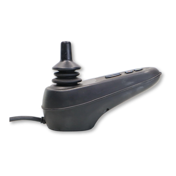
2. VR2 Lights 3. VR2 Seats&Lights 4. VR2 Attendant steering VR2 by PG Drives Technologies is a collective name for the entire control system of the wheelchair. The wheelchair is operated by means of a controller. Main components of the controller can be found in chapter 2.3. -
Page 8: Main Components
The controller F1+F2 2.3 Main components Part Function A. Joystick In the ´drive´ mode: driving and steering In the ‘adjustment options’ mode: • Left/right to select the adjustment options • Front/back to select the adjustment mode B. On/off switch Switching the controller on or off C. - Page 9 The controller Part Function L. User/attendant switch Switching between user and attendant controller M. User/attendant indicator Displays the active controller...
-
Page 10: Driving The Wheelchair
Driving the wheelchair Driving the wheelchair 3.1 Switching the controller on or To be able to drive or operate the electronic adjustment options of the wheelchair, the controller must be switched on. Press the on/off button (B in fi gure 5). Note! The joystick should be released (neutral position) when switching on the controller... -
Page 11: Speed
Driving the wheelchair 3.4 Speed The maximum speed can be controlled by the speed regulator on the controller (F1 en F2 in fi gure 5). The maximum speed is displayed by the LED lights above the speed regulators. Speed can be controlled with the joystick while driving. -
Page 12: The Electrical Adjustment Options
If you adjust the seat height by using the high/low option or use the electrical tilt adjustment 0 - 45°, the speed will be reduced for your safety. To use electrical adjustment options, the VR2 Seats&Lights controller is required (maximum of two options). 4.1 Selecting and operating the electrical adjustment option 1. - Page 13 The electrical adjustment options Move joystick backwards / Adjustment Pushing the push handles down Tilt The entire chair will tilt backwards High/low The entire chair will be raised Backrest The backrest will tilt backwards Legrest The legrest angle will increase, the footplate will be raised Move joystick forwards / Adjustment...
-
Page 14: Lights
Lights Lights Not every wheelchair has been equipped with lights. You can activate the following functions only by using VR2 Lights and/or VR2 Seat&Lights: Lights (I in fi gure 5) Hazard Lights (J in fi gure 5) Direction indicators (K1 & K2 in fi gure 5) -
Page 15: Troubleshooting
Malfunctions list An extended malfunction list can be found in the appendix of the service manual (for qualifi ed specialists only). The service manual can be found on www.handicare.com... -
Page 16: Locking The Controller
Locking the controller Locking the controller To lock the controller; While the control system is switched on, depress and hold the on/off button. After 1 second the control system will beep. Now release the on/off button Defl ect the joystick forwards until the control system beeps. -
Page 17: Technical Specifi Cations
1A max. Charger Connector Use only Neutrik NC3MX Batt. Charging Current 12Arms max. Actuator Current 12A max. Maximum Drive Current VR2 50 50A VR2 60 60A VR2 70 70A VR2 90 90A Moisture Resistance IPx4 Operating Temperature -25°C to +50°C Storage Temperature -40°C to +65°C... -
Page 18: Technical Diagrams
Technical diagrams Technical diagrams 9.1 Technical diagram The technical diagrams can also be found on the cover of the specifi c electronic component. 70 A Fuse lights left joystick lights right 1008386 VR-2 Lighting module... -
Page 19: Technical Diagram Battery Charger
Technical diagrams seat RWD seat FWD motor battery motor 9002474 VR-2 90A Powermodule mounting holes 1008388 VR-2 90A Powermodule twin actuators 9006377A 9.2 Technical diagram battery charger The controller’s standard confi guration includes a ‘3-pin connection’. Ensure that the battery charger is properly connected so that the ‘negative pole’... - Page 20 Dealer: Serial number:...

Need help?
Do you have a question about the VR2 and is the answer not in the manual?
Questions and answers