Table of Contents
Advertisement
Advertisement
Table of Contents

Summary of Contents for Moore FDY
- Page 1 November 2013 PC-Programmable Frequency Transmitter and Display 165-730-00E1...
-
Page 2: Table Of Contents
About this Manual ........................3 Specifi cations ....................4 PC Confi guration Software ................6 Programming the FDY ..................8 Connecting the FDY to the PC .....................8 Programming the Basic Parameters ..................9 Programming the Input Parameters ..................9 Programming the Range Parameters .................10 Programming the Output Parameters ................11... -
Page 3: The Fdy
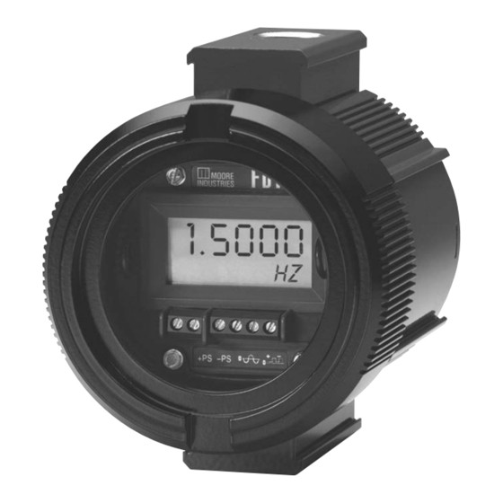
FDY features a large integral display that shows safety risks to personnel. real-time process status. Figure 1. The FDY Accepts a Frequency Signal and Outputs a Scaleable 4-20mA Signal eight Measurement Device... -
Page 4: Specifi Cations
Common mode, 120dB confi gurable resistor typical@100mVp-p input Overcurrent Limiting: 25mA maximum Weight FDY HP: 227g (5.3 oz) Maximum Voltages: 48Vdc FDY in BH housing with output, maximum; DC glass cover: 1.45kg input, 48Vdc, maximum; AC (3 lbs, 12.4 oz) - Page 5 0.0015 0.0026 0.0034 0.1 Sec *Combine Input-to-Display and Display-to-Output values to determine overall stability. **Consult factory for improved long-term drift specifi cations. Table 2. DC Input Range and Accuracy for All FDY Models Input Range Min. NOTE: Accuracy Input Type...
- Page 6 PC-Programmable Frequency Transmitter and Display Figure 2. FDY Dimensions SIDE VIEW FRONT VIEW 76mm 66mm (3.00 in) (2.58 in) 61mm (2.40 in) 83mm (3.25 in) 6027.8 18mm (0.70 in) 62mm (2.45 in) + – –PS 43mm (1.70 in) 64mm (2.50 in) Figure 3.
-
Page 7: Pc Confi Guration Software
Tabs–These tabs change the right side of the screen ID number. to allow you to set the appropriate part of the FDY’s confi guration. See corresponding sections of this 2. Tag/Descriptor/Message–These boxes are used manual for additional information on these tabs. - Page 8 PC-Programmable Frequency Transmitter and Display Figure 5. All of the FDY Operating Parameters can be set from the Main Screen of the Confi guration Program. Default/Factory Confi gurations The following are the default factory settings for your unit: Input: Measurement Mode: Frequency 0-100Hz...
-
Page 9: Programming The Fdy
Connecting the FDY to the PC Communications Version 1.0 or greater, Software The fi rst step in confi guring the FDY is connecting part number: 750-75E05-01 the transmitter to the PC program and attaching the appropriate input devices. Connect the FDY as shown in Figure 6 below;... -
Page 10: Programming The Basic Parameters
PC-Programmable Frequency Transmitter and Display Programming the Basic Parameters AC / DC Input: Select the type of input the FDY will measure. Programming the Basic Parameters involves selecting the desired parameters in the PC Program, then Input Threshold: Input threshold is applicable to DC downloading those parameters to the FDY. -
Page 11: Programming The Range Parameters
Averaging Filter: Shows the number of readings when the input will be considered bad (over or the FDY averages together to provide the displayed under range). For example, if you have set the reading. This can be used to compensate for bent... -
Page 12: Programming The Output Parameters
PC-Programmable Frequency Transmitter and Display Programming the Output Output Settings The output can be reversed (causing the output to Parameters increase as the input decreases) by setting the Lower The Output section of the PC software is composed Range Value in the Range tab as higher than the of three sections: Output Settings, Failure Mode and Upper Range Value (See Figure 8). -
Page 13: Programming The Trimming Parameters
Set Value box under Point 2 and click Set. Then apply the value you entered in the Point 2 box to the FDY. Click on the Trim Pt 2 button. This matches the signal from the sensor to the second point you selected. -
Page 14: Output Trimming
1. To begin the loop test, enter the mA value you want it will eliminate any error in the unit that is reading the the FDY to output to the Loop into the Loop Test text FDY’s output. box. Click Fix. -
Page 15: Programming The Custom Curve Parameters
Display EGU label box. This will control what type of engineering unit (up to 5 alphanumeric characters, excluding symbols) is displayed by the Confi guration Software and on the FDY’s display. 4. Click Set to download all of the information to the transmitter. -
Page 16: Editing The Custom Curve Table
X column is input. It is power. also the value that will be displayed in the PC Software and on the FDY display. If an input falls in between two Mounting X values, then the output will be scaled to match the The FDY is built in a HP housing and can be shipped percentage difference between the two X points. -
Page 17: Customer Service
The shield should be grounded at the receiver and not at the signal source. Figure 12. Hook-Up Diagram for Installing the FDY into the Application 6027.8 + – –PS... -
Page 18: Appendix-A Intrinsically-Safe Applications
Special Conditions of Use The following instructions must be adhered to when the FDY is used in hazardous ‘Classifi ed’ locations and potentially explosive atmospheres. 1. The FDY Power Supply/Output must only be connected to a intrinsically-safe certifi ed Barrier or other associated apparatus. - Page 19 PC-Programmable Frequency Transmitter and Display The Interface Solution Experts...
- Page 20 Page 1 of 2 Equipment Description: PC-Programmable Frequency-to-DC Transmitter with Display Model FDY / * / * / * / * / * * Indicates any input, output, power, options and housing as stated in the product data sheet. Directive: 2004/108/EC (EMC)
- Page 21 Chester, Cheshire, CH4 9JN, England On Behalf of Moore Industries-International, Inc., I declare that, on the date the equipment accompanied by this declaration is placed on the market, the equipment conforms with all technical and regulatory requirements of the above listed directives.
- Page 22 4. Ship the equipment to the Moore Industries location nearest you. The returned equipment will be inspected and tested at the factory. A Moore Industries rep- resentative will contact the person designated on your documentation if more information is needed.
Need help?
Do you have a question about the FDY and is the answer not in the manual?
Questions and answers