
Summary of Contents for Sun-Tech ST-PRO101 PRO-ONE
- Page 1 Sun-Tech PERATION ANUAL PRO-ONE AV CONTROLLER ST-PRO101 Model: Operation Manual Version: 5.1 Page 1 ~ 24 Page 1...
- Page 2 This device complies with Part 15 of the FCC Rules. Operation is subject to the following two conditions: (1) this device may not cause harmful interference, and (2) this device must accept any interference received, including interference that may cause undesired operation.
- Page 3 Welcome…… and thank you for purchasing this Sun-Tech PRO-ONE A/V Controller. This state of the art system includes everything you need to experience high quality digital video and audio in your multimedia learning environment. We have designed this system to be easy to set up, and even easier to operate.
-
Page 4: Table Of Contents
Table of Contents Index to Parts and Controls 4 ~ 5 Important Safeguards and Precautions Features of this System Important Information Regarding This Manual 1. Installations 1.1 Unpacking 1.2 Speaker System Connection 8 ~ 9 1.3 AV Equipments Input/Output Signal Connections 10 ~ 12 1.4 Teacher PC and Laptop Connections 13 ~ 15... -
Page 5: Index To Parts And Controls
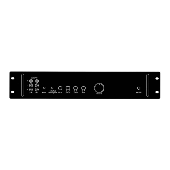
Index to Parts and Controls Front Panel: Refer to the pages indicated in parentheses for details. 1. Audio, Video Composite Inputs (page 12) 6. Master Treble Level Control (page 18) 2. Power ON/OFF Indicator (page 18) 7. Master Bass Level Control (page 18) 3. - Page 6 Index to Parts and Controls (Continued) Rear Panel: Refer to the pages indicated in parentheses for details. 1. Voltage Selector (page 18) 6. VGA Input/Output Terminals (page 14, 15, 17) 2. AC Power Plug (page 17) 7. PRO-ONE Control Terminals (page 14) 3.
-
Page 7: Important Safeguards And Precautions
Important Safeguards and Precautions Power Cord Protection To avoid any malfunction of the unit, and to protect against electric shock, fire or personal injury, please observer the following: Hold the plug firmly when connecting or disconnecting the AC power cord. Keep the AC power cord away from heating appliances. -
Page 8: Features Of This System
Features of This System 7-channel A/V input 3-channel A/V output 1-channel microphone input 2-channel VGA input 1-channel VGA output with VGA connector x 2 (splitter) 50 W power amplifier with speaker outputs Programmable Infrared remote control (I/O) Mic volume, Master volume, treble and bass level control Power supply: 100-115/230V (user selectable) Rack Mountable Important Information Regarding This Manual... -
Page 9: Installations
1. Installations This section describes how to connect the system to the speakers, projector, Teacher PC, Laptop computer and others AV equipments. Be sure to turn off the power of each component before making the connections. 1.1 Unpacking Check that you have the following items: 1 x Main unit 1 x VGA cable 1 x RS-232 cable (control cable, female to male) - Page 10 To avoid short-circuiting the speakers Make sure the stripped end of each speaker cord does not touch another speaker terminal or the stripped end of another speaker cord. Examples of poor connection of the speaker cord Stripped cords are touching each other Stripped speaker cord is touching due to excessive removal of insulation.
-
Page 11: Av Equipments Input/Output Signal Connections 10
1.3 AV Equipments Input/Output Signal Connections Equipments mentioned in this section: DVD player Cassette Player VHS Player Digital Video Camera (DV Cam) Required cords Composite video cords (male to male) Composite audio cords (male to male) Infrared transmitter with cable and jack The following table is the recommended Note: AV Input Channel... - Page 12 Connection Diagram (1): Cassette Tape Player/Recorder Audio Left In Audio Right In PRO-ONE Point the Infrared transmitter towards those AV equipments. Video Out Infrared Transmitter Audio Left Out Audio Right Out Page 12...
- Page 13 Connection Diagram (2): PRO-ONE Video Out Video Out Audio Left Out Audio Left Out Audio Right Out Audio Right Out DV Camera Visualizer Page 13...
-
Page 14: Teacher Pc And Laptop Connections 13
1.4 Teacher PC and Laptop Connections Equipments mentioned in this section: Teacher PC Laptop Computer (Optional) Required cords Composite video cords (male to male) Audio cable (1 x 3.5mm stereo male to 2 x composite male) Stereo 3.5mm splitter (1 x 3.5mm male to 2 x 3.5mm female) RS-232 Serial Cable (Straight-through) (female to male) VGA cable (male to male) Note:... - Page 15 Teacher PC Connection Diagram: Label Description VGA signal output from the video card in the Teacher PC. Line Out from the sound card in the Teacher PC. (Optional) Composite video and audio signal input to the WinFast MPEG encoder card in the Teacher PC. Serial interface (COM1) of the Teacher PC.
- Page 16 Laptop Computer Connection Diagram: Laptop PRO-ONE Label Description VGA signal output from laptop computer* Line Out from the sound card in the laptop computer. Note: Please make sure you have selected to output the video signal to the VGA output port at the back of the laptop computer.
-
Page 17: Projector And Auxiliary Connections 16
1.5 Projector and Auxiliary Connections Equipments mentioned in this section: Projector Required cords Composite video cords (male to male) Composite audio cords (male to male) Infrared transmitter with cable and jack VGA cable (male to male)* *Note: This VGA cable should come with your projector. AV Output Channel AV Equipment Channel -1... -
Page 18: Ac Power Connection
Projector Connection Diagram: Video In Composite Video In Point the Infrared transmitter towards projector. PRO-ONE 1.6 AC Power Connection Notes Connecting to inappropriate power may damage the system or cause abnormal operation. (please refer to the voltage selection guide on page 18) Before connecting the AC power cord of this system to a wall outlet, connect the speakers and other component cables to the system. -
Page 19: Basic System Setup And Operations
2. Basic System Setup and Operations This section explains how to properly setup PRO-ONE to be used in different countries. Also, some basic function will be described. 2.1 Voltage Selection Before turning on the unit, please select the appropriate voltage setting for PRO-ONE. FAIL TO DO SO MAY CAUSE PERMEMNENT DAMAGE TO PRO-ONE. -
Page 20: Microphone Input And Control
2.3 Microphone Input and Control A 6.3mm mono microphone jack named “Mic. In” is located on the front panel. Connect it with a microphone if you need. (please refer to the “Front Panel” view on page 4) Adjusting the microphone Volume: On the front panel: To increase the microphone volume level, turn the “Mic. -
Page 21: Settings And Adjustments
3. Settings and Adjustments This section explains how to use the “AV Infrared Learning Program” to program PRO-ONE in order to control other AV equipments. 3.1 Programming the Infrared Controller Before you start using your PRO-ONE AV control system, you have to “teach” PRO- ONE how to control those AV devices. -
Page 22: Additional Information
A.1 Troubleshooting If you experience any of the following difficulties while using the system use this troubleshooting guide to help you remedy the problem. No power. (Power Indicator is off) Is the power cord firmly plugged into the power outlet? One of the safety mechanisms may be operating. -
Page 23: Technical Specifications
A.2 Specifications Slew rate: 1100V/μs Bandwidth: 250MHz (@ -3dB) R to G to B: 0.10dB Gain Matching: Input 1 to Input 2: 0.01dB 2-channel standard VGA signal Input: Connectors: DB-15 (female) x 2 2-channel synchronized VGA signal Output: Impedance: 75 ohms Connectors: DB-15 (female) x 2 Cross-talk:... - Page 24 SUN-TECH International Group Limited Sun-Tech International Group Limited Distributor: 22/F, 9 Chong Yip Street, Kwun Tong, Kowloon, Hong Kong Tel.852-27830868 Fax.852-27806644 Email: sales@suntechgroup.com Page 24...
Need help?
Do you have a question about the ST-PRO101 PRO-ONE and is the answer not in the manual?
Questions and answers